The hardware enthusiast's corner
Message boards :
Number crunching :
The hardware enthusiast's corner
Message board moderation
Previous · 1 . . . 11 · 12 · 13 · 14 · 15 · 16 · Next
| Author | Message |
|---|---|
|
Send message Joined: 13 Dec 17 Posts: 1424 Credit: 9,189,946,190 RAC: 2 Level Scientific publications |
Or spiderwebs on the electronics allowing dust to glom onto parts and connections. I had to "debug" my weather station outside sensor array last summer to get rid of spurious readings and glitches. |
 ServicEnginIC ServicEnginICSend message Joined: 24 Sep 10 Posts: 595 Credit: 13,083,686,510 RAC: 745,928 Level Scientific publications |
 |
|
Send message Joined: 13 Dec 17 Posts: 1424 Credit: 9,189,946,190 RAC: 2 Level Scientific publications |
Hahah ha LOL. I would have changed the labeling of "patiently" to "im-patiently" What else ya gonna do . . . . twiddle your thumbs . . . . or dig around in the bit box and scramble something up to keep your mind active. |
|
ServicEnginIC Send message Joined: 24 Sep 10 Posts: 595 Credit: 13,083,686,510 RAC: 745,928 Level Scientific publications |
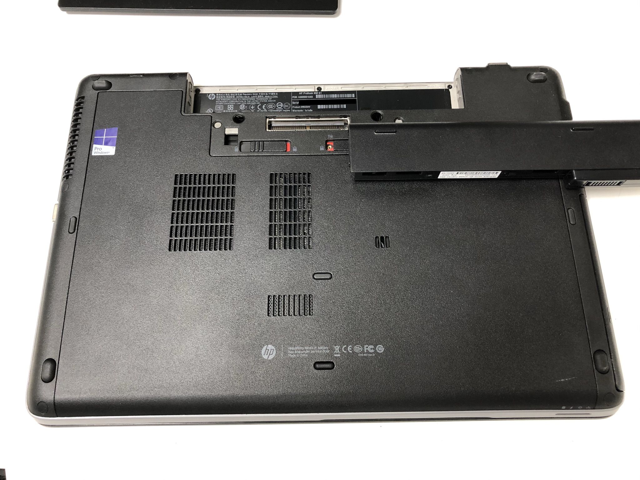
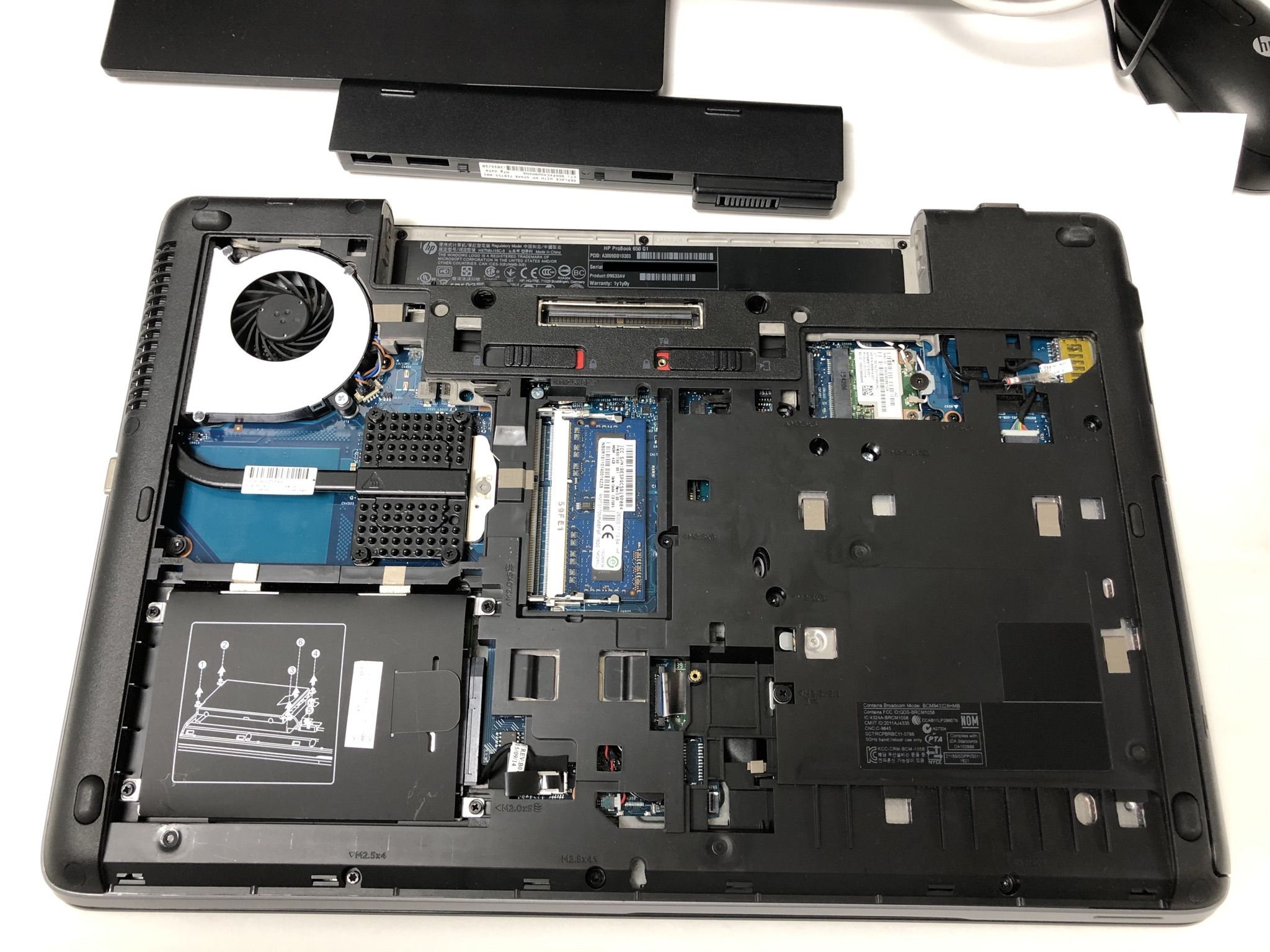
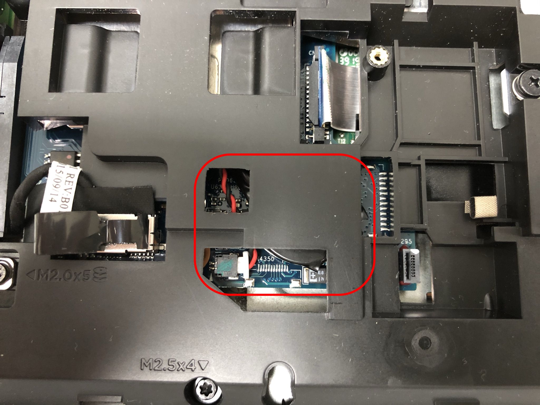
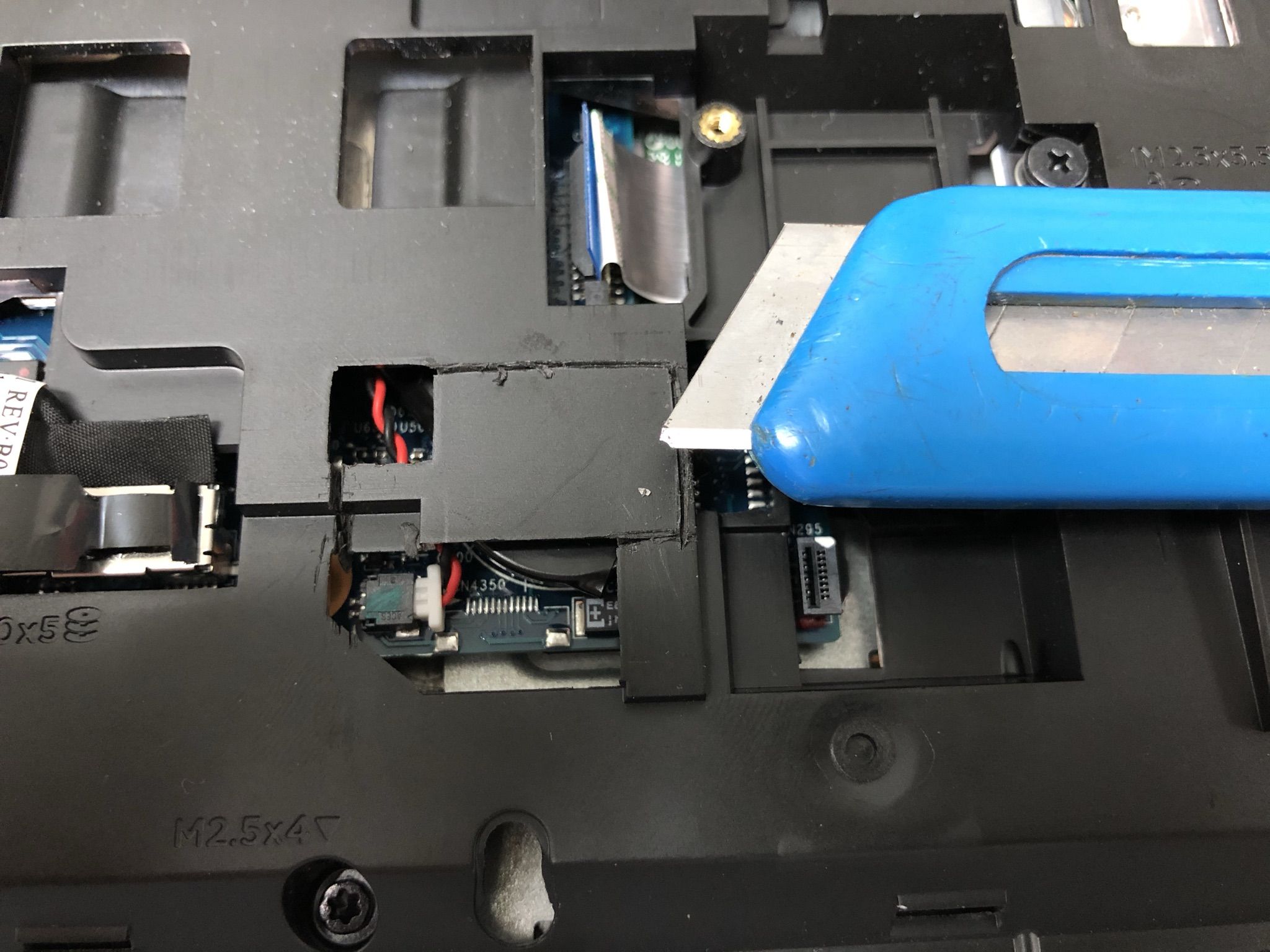
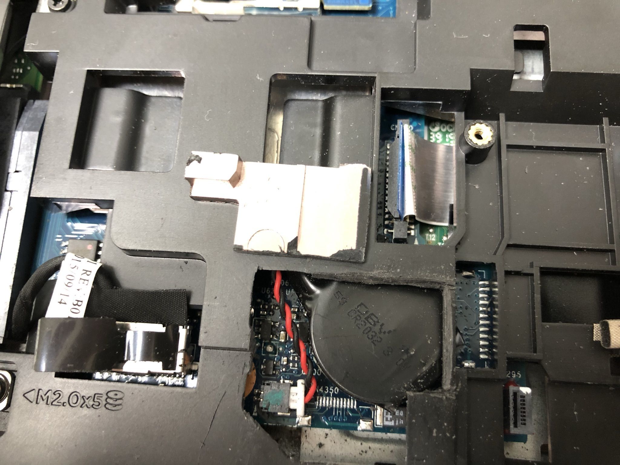
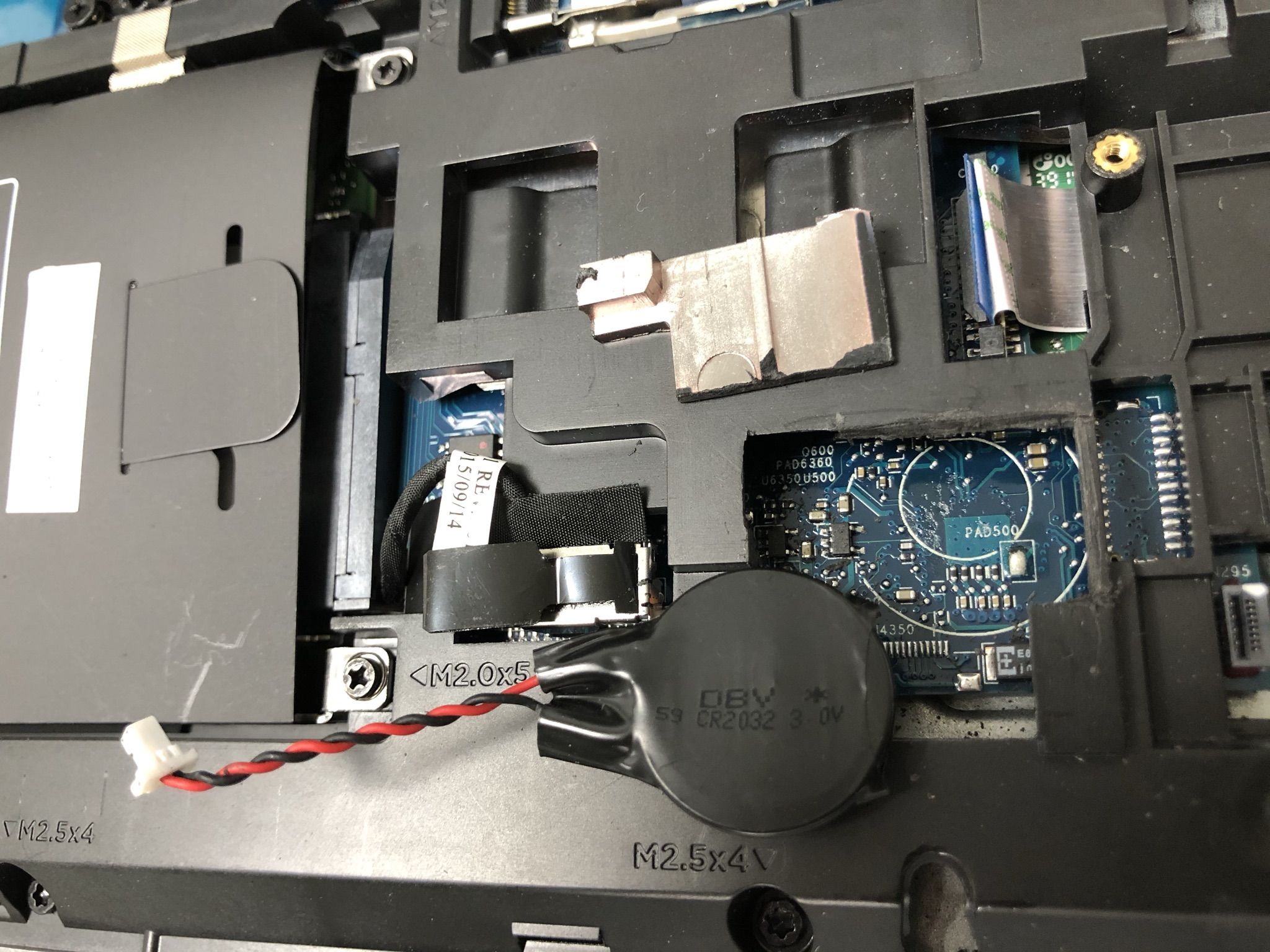
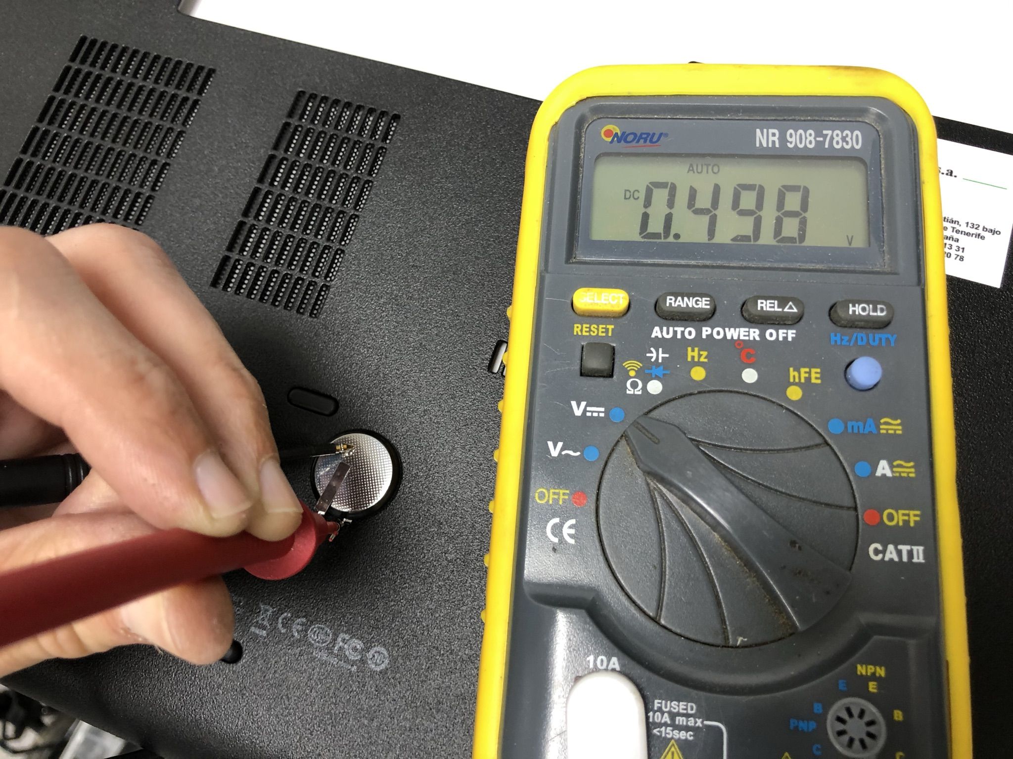
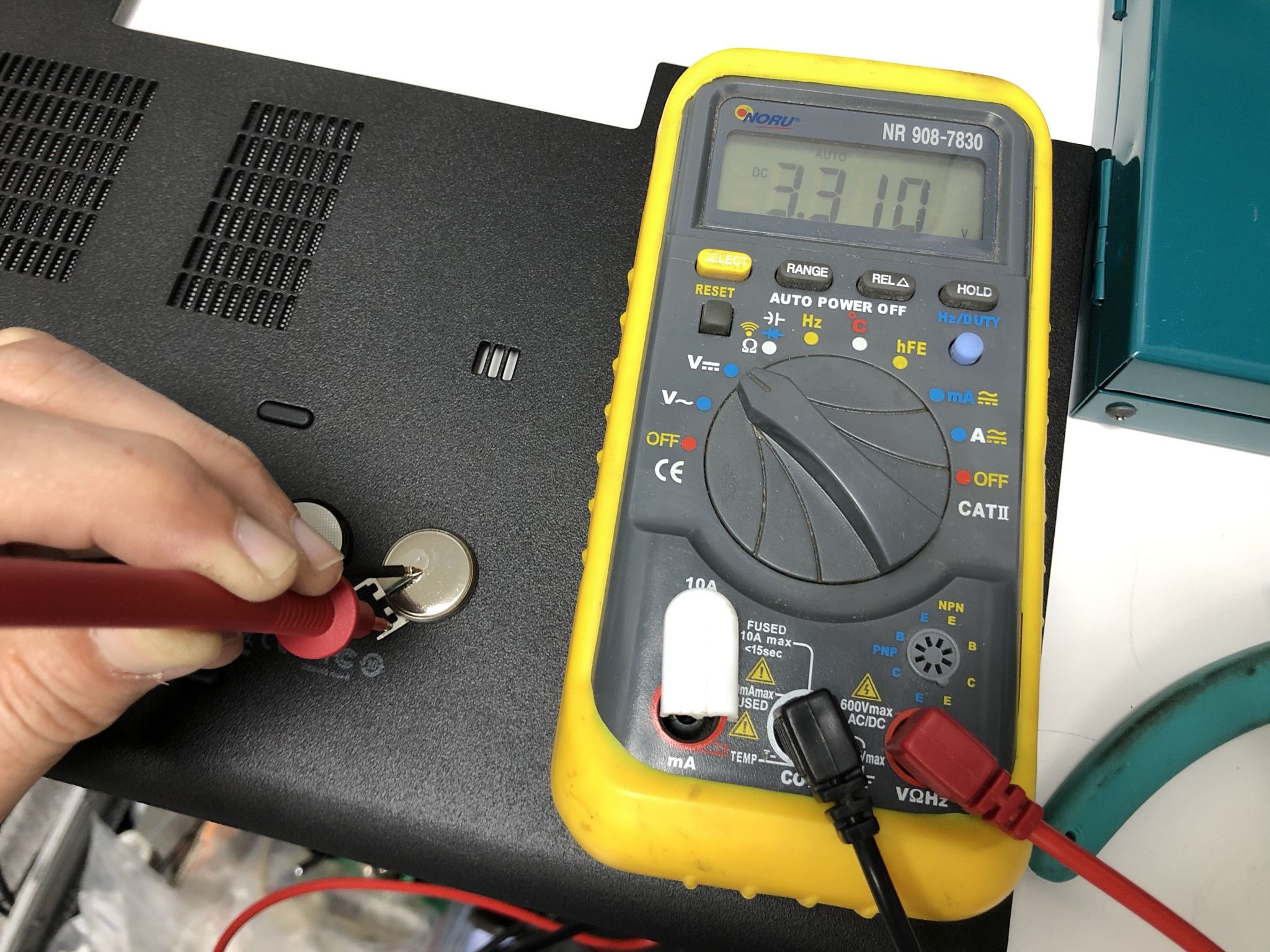
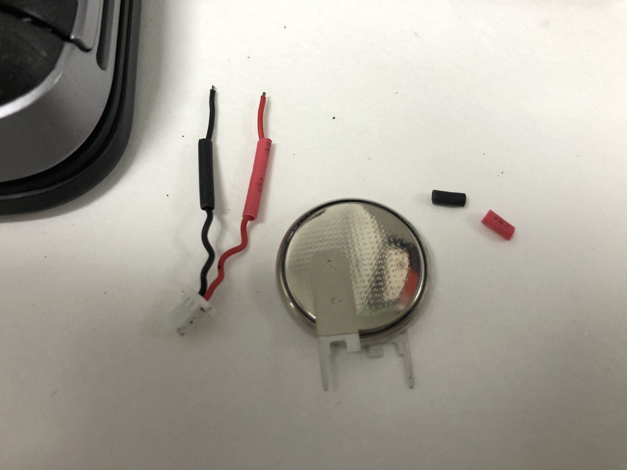
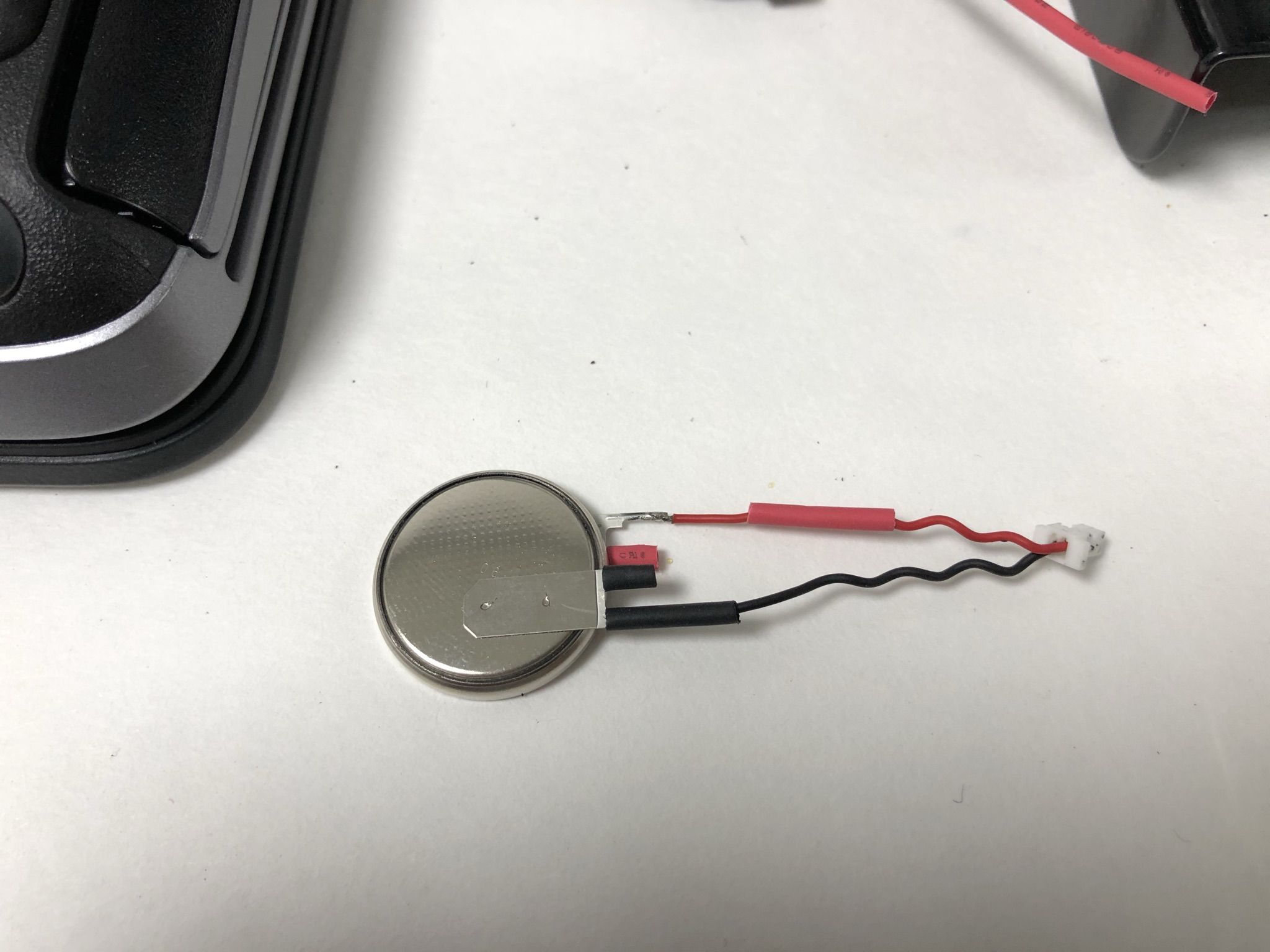
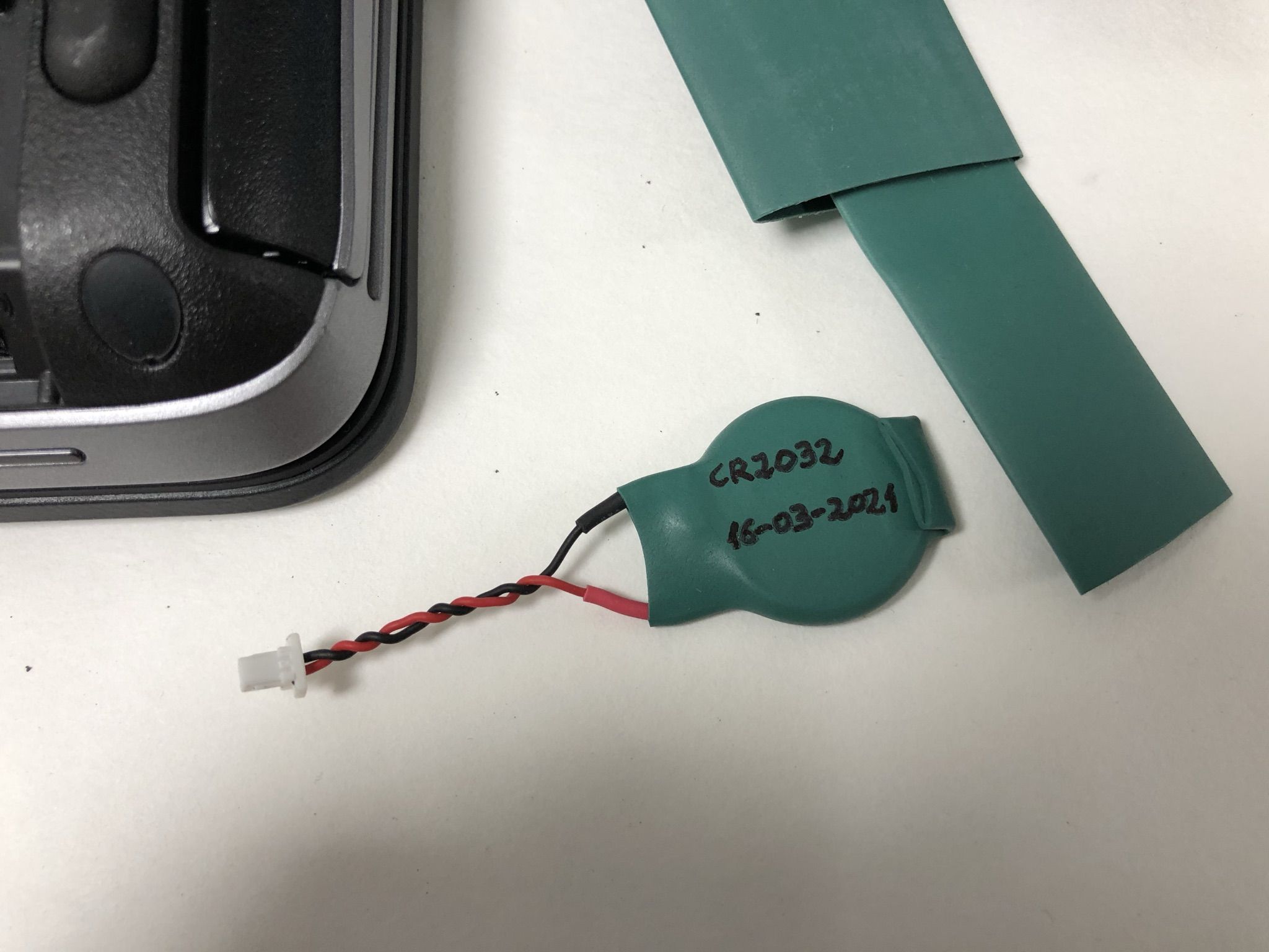
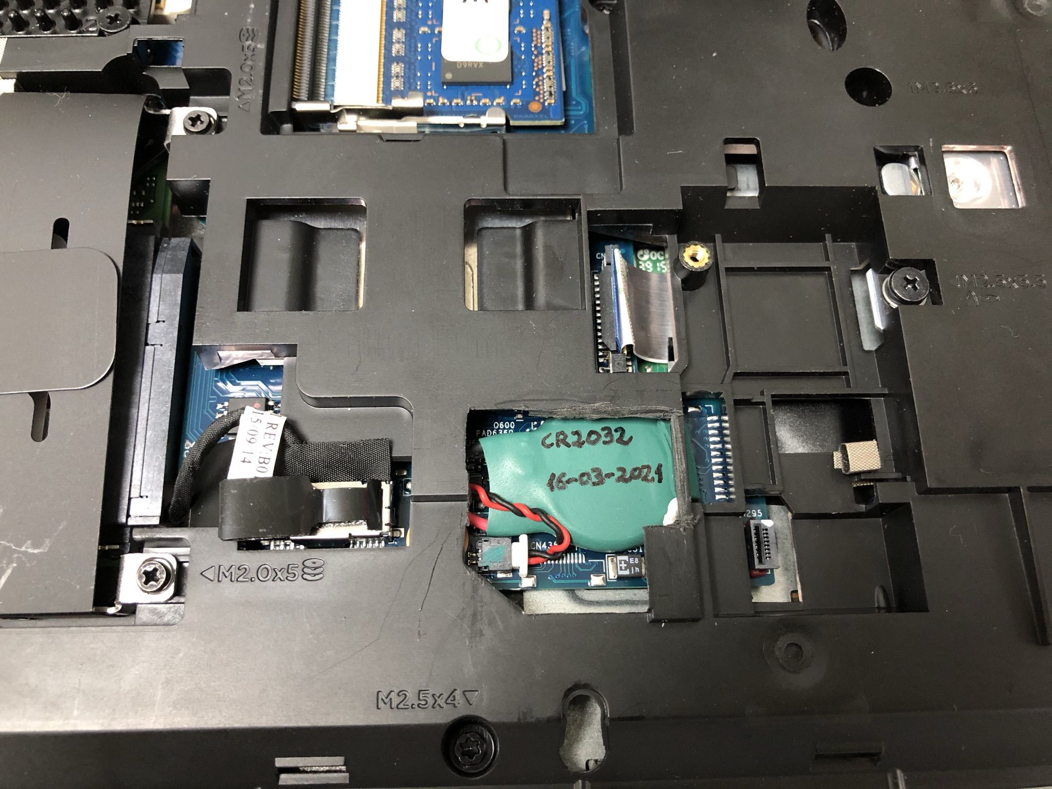
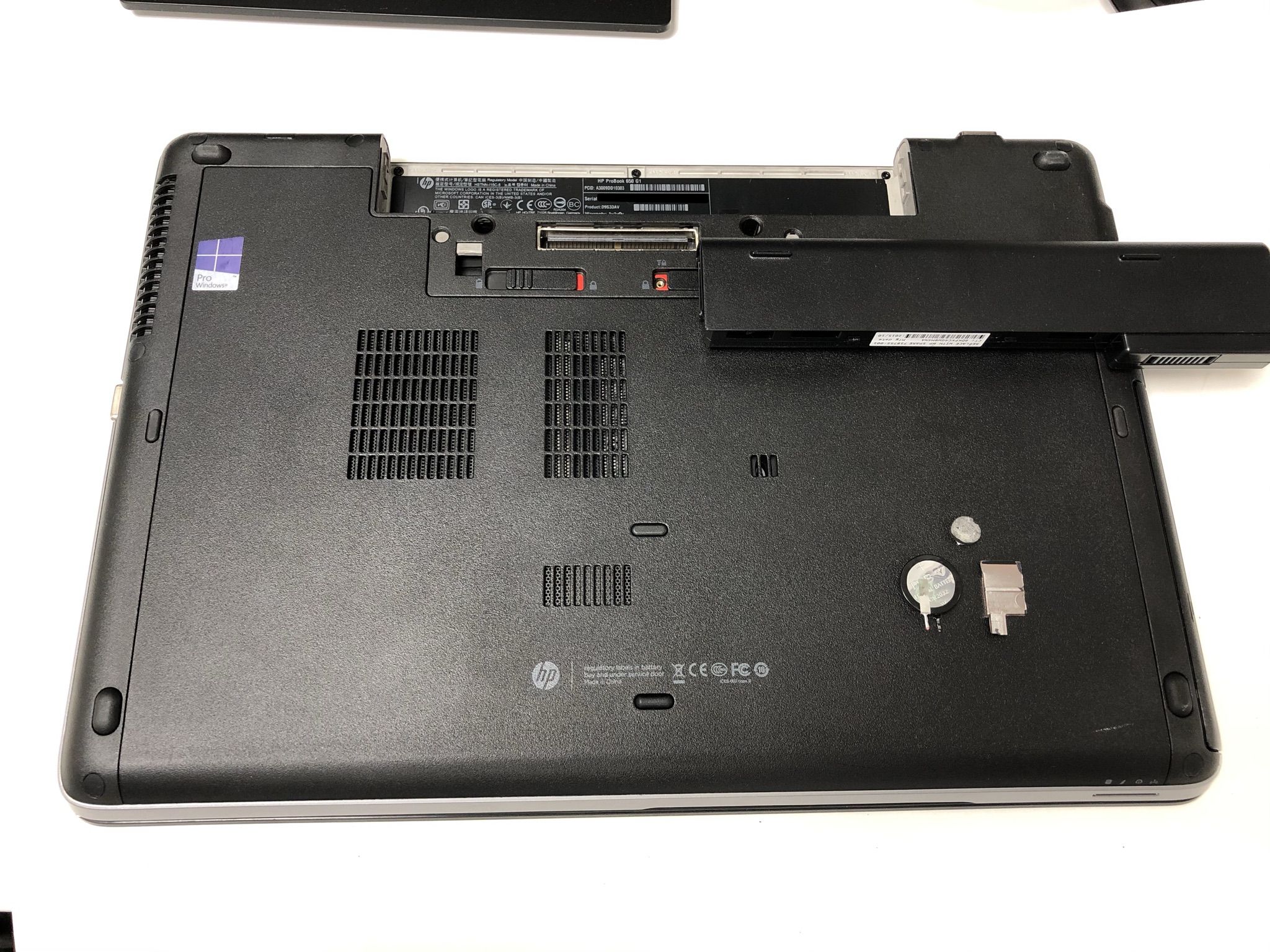
Laptops Design Engineers LOL I recently discovered the meaning of LOL (Thank you, Keith) I had seen it mentioned here and there, but I entered Wikipedia in search of its meaning, and it is the acronym of "Laughing Out Loud" Then I thought that perhaps it might have been developed by laptops Design Engineers, thinking about Field Service Engineers for laptops: "I managed to compact all these small things inside this, now I want to see how are you managing to service it, hahahaaah LOL" One example can be seen at the next HP Support video, regarding how to exchange the Real Time Clock and BIOS setup backup battery. https://www.youtube.com/watch?v=nuy0gA38G1I I had to exchange this battery in a laptop that was causing problems due to spontaneous CMOS memory corruption and RTC returning to 1/1/2000 when main battery was unplugged. Life for these backup batteries is about three to five years. Therefore, when they become exhausted, usually product warranty has expired... Here we have the problematic laptop. After removing the bottom cover by actuating over the opening levers, we get this inside panorama. A close look shows that the RTC battery is enclosed under an intermediate frame, as seen in previous video. If I can evite to dismount the whole laptop to gain access to replace the battery... I'll do! ... How? I'm opening an imaginary window on the intermediate frame, wide enough to easily remove the old battery and replace it by the new one. Here we have the window opened, and battery to be replaced is at sight, protected with an insulating shroud. This is the battery out of home through the window. It is a 3V CR2032 lithium battery, not a regular, but a wired one. In a quick check, voltage for the old battery shows 0.498 Volts: It is completely dead. Checking the replacement new battery, the reading is 3.310 Volts. This is the normal value for a new one. The second half of the intervention consists of recovering the original cables and connector and implant them to the new battery. Here is half the way, and later a covering of thermo shrinking sleeve is applied for a perfect isolation. The new battery is then replaced into position, and ready for the photo finish. This time there were neither leftover nor missing screws... because it wasn't necessary to unscrew any! L😂️L |
|
Send message Joined: 13 Dec 17 Posts: 1424 Credit: 9,189,946,190 RAC: 2 Level Scientific publications |
You were fortunate for having a little glimpse of the battery and cable through that aperture. If it would have not been at least partially exposed you would have had to dismantle the backside covering to find the battery location. And now future battery replacement is just as easy. Smart idea to notate the date of replacement. |
|
ServicEnginIC Send message Joined: 24 Sep 10 Posts: 595 Credit: 13,083,686,510 RAC: 745,928 Level Scientific publications |
 |
|
ServicEnginIC Send message Joined: 24 Sep 10 Posts: 595 Credit: 13,083,686,510 RAC: 745,928 Level Scientific publications |
 |
|
ServicEnginIC Send message Joined: 24 Sep 10 Posts: 595 Credit: 13,083,686,510 RAC: 745,928 Level Scientific publications |
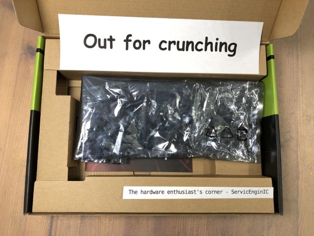
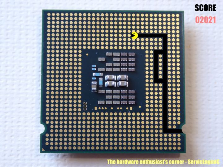
A couple of notes about the previous image: -1) If you thought that the main motif is familiar to you, you're right. It is the back of the package of a LGA775 socket Intel processor. More specifically, an Intel Core 2 Quad Q8400 -2) Regarding the score shown: 02021 2021 might appear to be a prime number, but it is not. It is composed by two factors: 43 and 47 Pacman has eaten 43 round terminals, 47 points each, this results in the 02021 score shown. Why a leading zero?.. If pacman ate all the 775 terminals, the final score would be 36425 points. 2021?.. What does that sound like to me? -3) It is proven that a lack of work like current, leads me to think of strange things. The dead time otherwise employed watching statistics... Yes! You're a really sharp observer: You have noticed that I said "a couple of notes", and finally it was three ;-) |
|
Send message Joined: 8 Aug 19 Posts: 252 Credit: 458,054,251 RAC: 0 Level Scientific publications |
Can anyone edify me on what effect the anti-mining feature now included on RTX30xx GPUs has on CUDA capability? They only talk about hash rate and my knowledge is lacking. Will these GPUs be slowed down running ACEMD tasks (once they are CUDA 1.2 updated) TIA for any tutoring! "Together we crunch To check out a hunch And wish all our credit Could just buy us lunch" Piasa Tribe - Illini Nation |
|
ServicEnginIC Send message Joined: 24 Sep 10 Posts: 595 Credit: 13,083,686,510 RAC: 745,928 Level Scientific publications |
Can anyone edify me on what effect the anti-mining feature now included on RTX30xx GPUs has on CUDA capability? ... I'd be interested on the same topic. Merely for information, since I'm not owning any graphics card based on Ampere GPUs so far. And no expectation of any coming in a near future, given that I've noted a crazy lack of last generation cards at local market. I took a look yesterday, and the most powerful card I found available was a GTX 1650 (Turing GPU series) graphics card... |
|
Send message Joined: 8 Aug 19 Posts: 252 Credit: 458,054,251 RAC: 0 Level Scientific publications |
...the most powerful card I found available was a GTX 1650 (Turing GPU series) graphics card... Same here in the US for the most part. You can get better cards if you want to pay way more than they used to be worth. Even the 1650s are overpriced, as mine were $140 US before all this madness. It seems the only way to get a powerful GPU is to buy a pre-built machine that includes it in the package, and very few appear to have Turing GPUs. Mostly Ampere in that market sector. Do they even still make Turing GPUs? "Together we crunch To check out a hunch And wish all our credit Could just buy us lunch" Piasa Tribe - Illini Nation |
|
Send message Joined: 21 Feb 20 Posts: 1117 Credit: 40,876,970,595 RAC: 0 Level Scientific publications |
Can anyone edify me on what effect the anti-mining feature now included on RTX30xx GPUs has on CUDA capability? They only talk about hash rate and my knowledge is lacking. Will these GPUs be slowed down running ACEMD tasks (once they are CUDA 1.2 updated) It wont have any impact on anything other than the Ethereum algorithm. The ETH algorithm (also known by its name, Dagger-Hashimoto, or sometimes referred to as ethash. this algorithm is very unique in how it works and makes it easy for nvidia to program detection into their GPUs. note, that Nvidia's "anti-mining" feature ONLY targets this algorithm, and other forms of mining on GPUs with other algorithms are NOT targeted. you can absolutely still use these GPUs with other mining algorithms unrestricted. this feature will not affect any form of CUDA/OpenCL compute workloads that are not using the ETH algorithm, that means that GPUGRID (or any other BOINC project) will not be affected. but of course, right now, it's all moot anyway, since the only cards that have this feature are Ampere cards, and Ampere cards dont work here on GPUGRID yet since the developers haven't updated the application to support them. 
|
|
Send message Joined: 8 Aug 19 Posts: 252 Credit: 458,054,251 RAC: 0 Level Scientific publications |
It wont have any impact on anything other than the Ethereum algorithm. That, hombre, is wonderful news for this project. The only missing factor is available time to upgrade ACEMD tasks to the latest CUDA. Or will that have to come from the software vendor? (As always, thanks for sharing your knowledge) "Together we crunch To check out a hunch And wish all our credit Could just buy us lunch" Piasa Tribe - Illini Nation |
|
ServicEnginIC Send message Joined: 24 Sep 10 Posts: 595 Credit: 13,083,686,510 RAC: 745,928 Level Scientific publications |
Can anyone edify me on what effect the anti-mining feature now included on RTX30xx GPUs has on CUDA capability? Nice to know. Thank you very much you both. |
|
ServicEnginIC Send message Joined: 24 Sep 10 Posts: 595 Credit: 13,083,686,510 RAC: 745,928 Level Scientific publications |
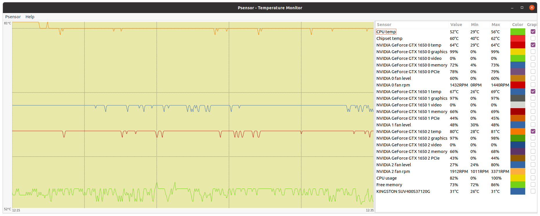
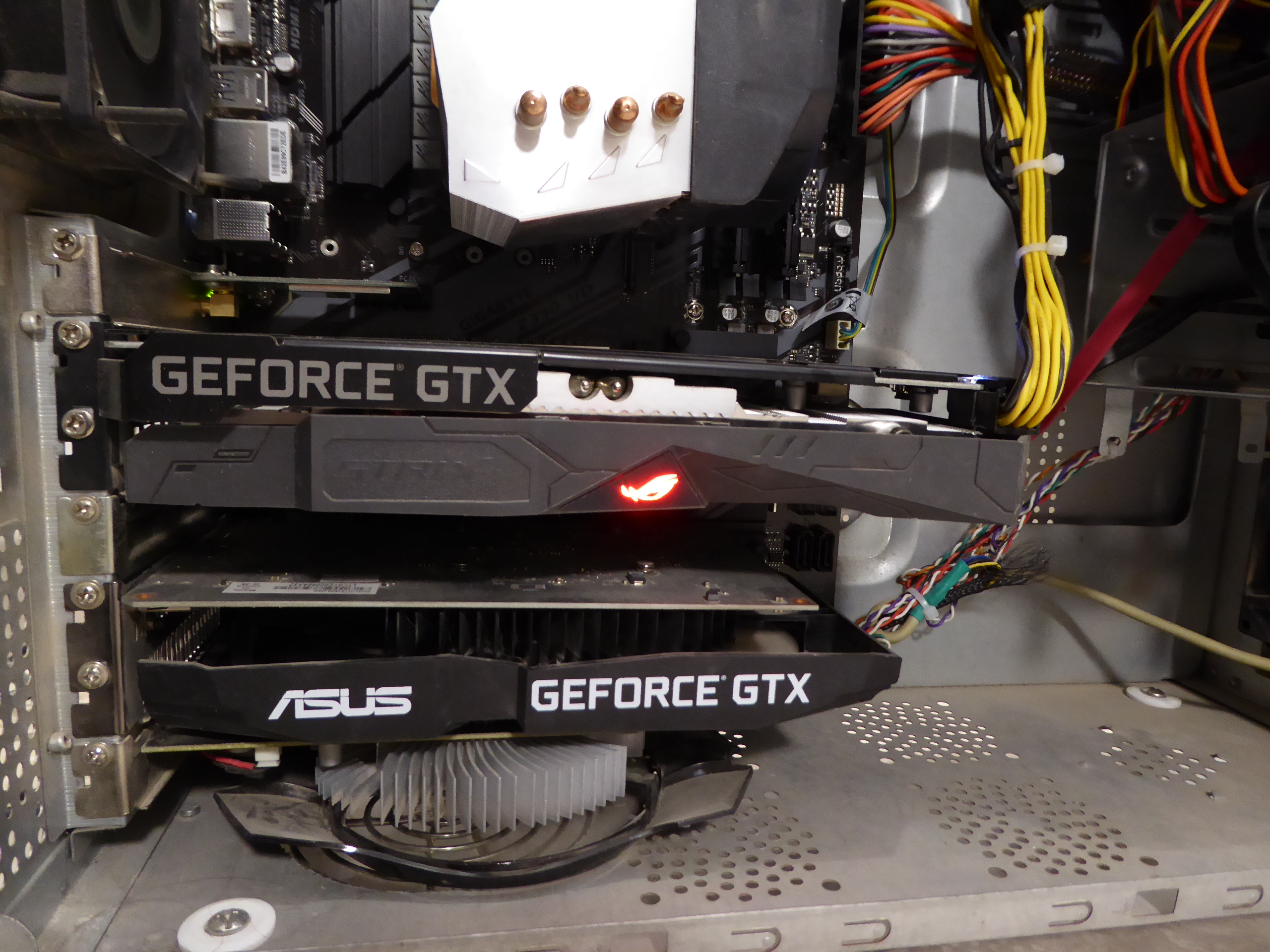
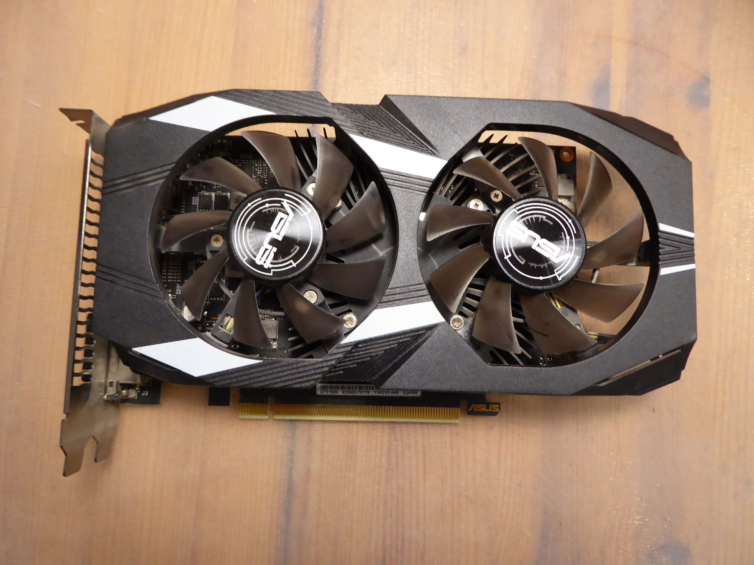
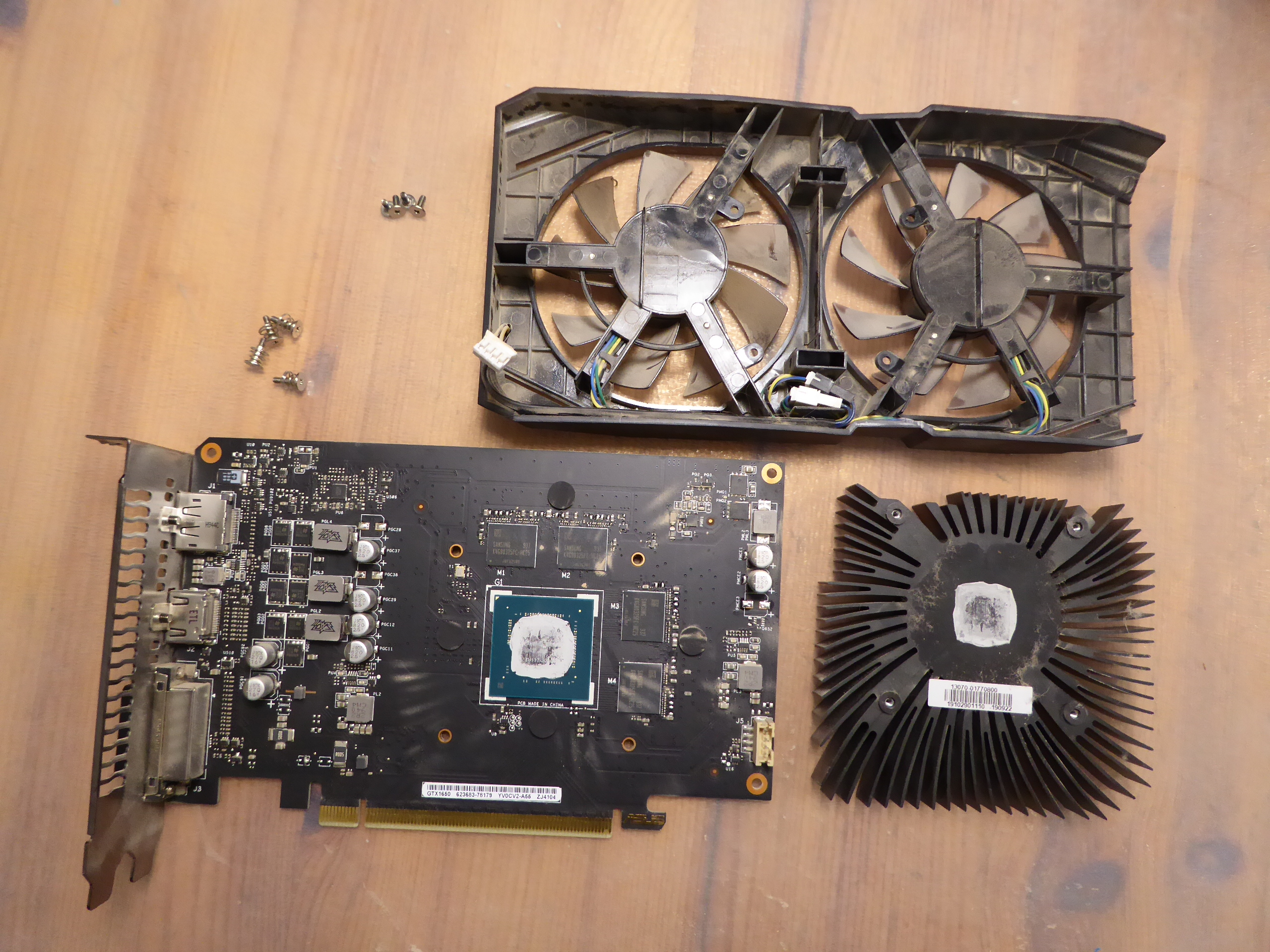
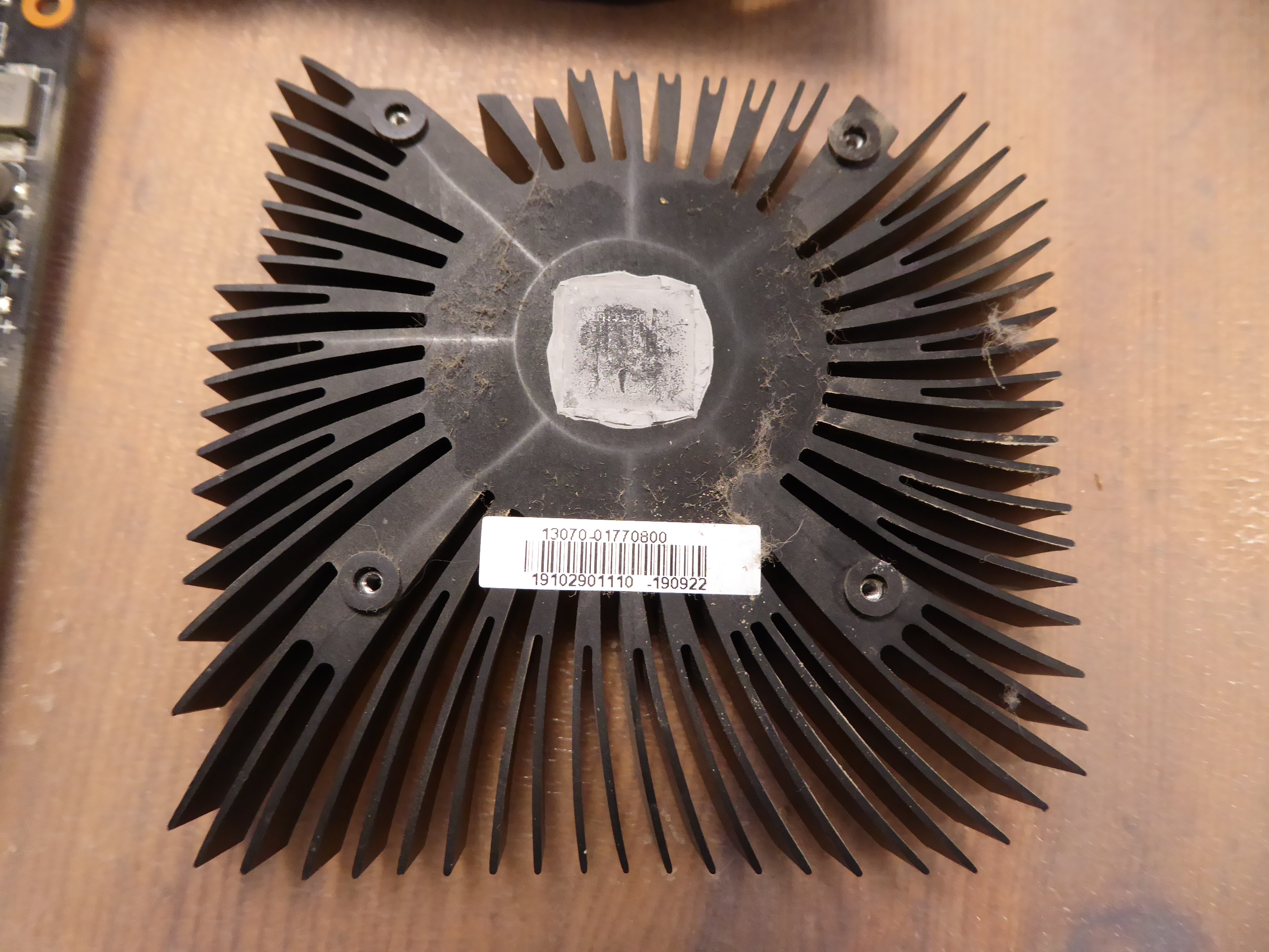
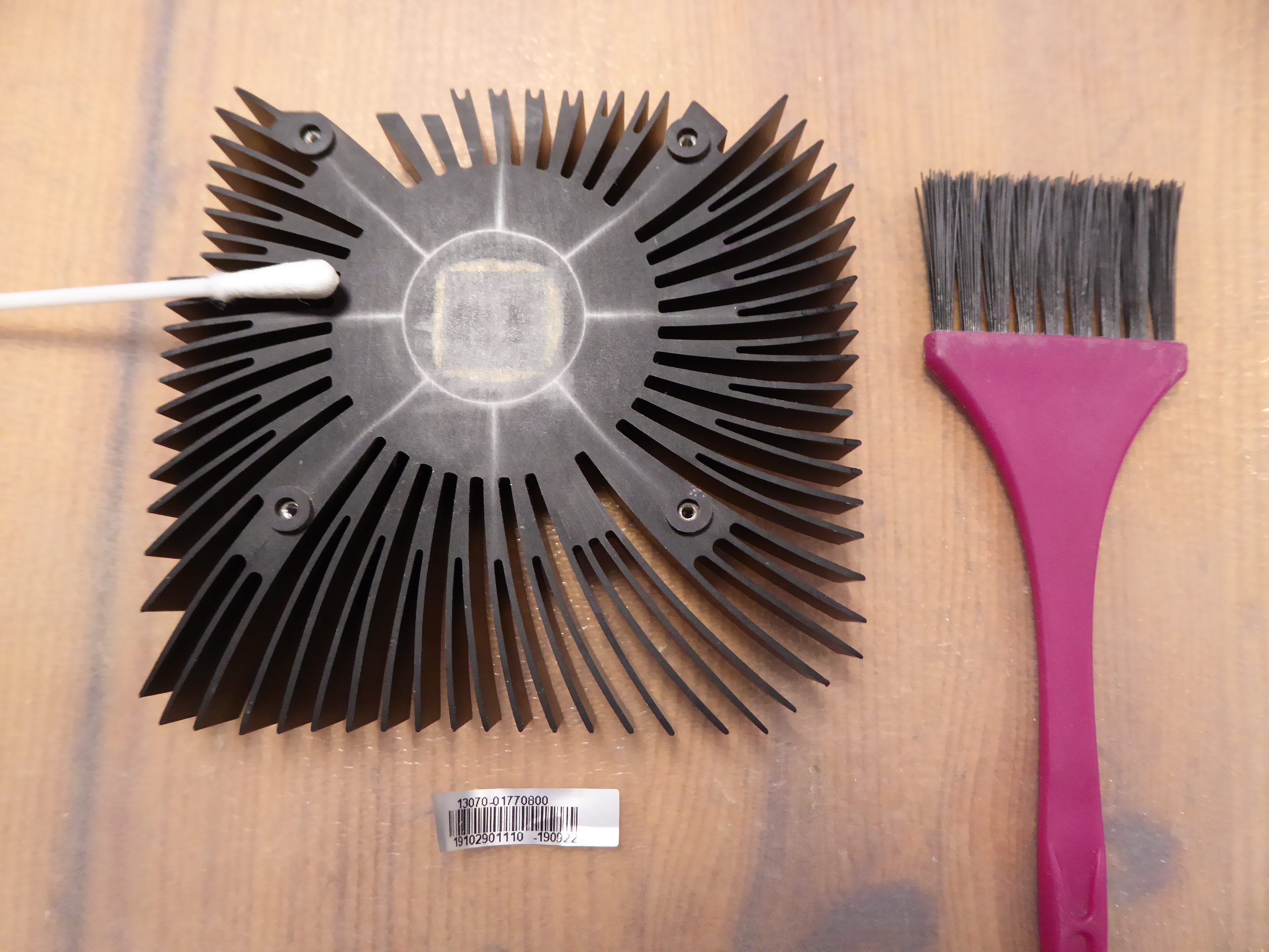
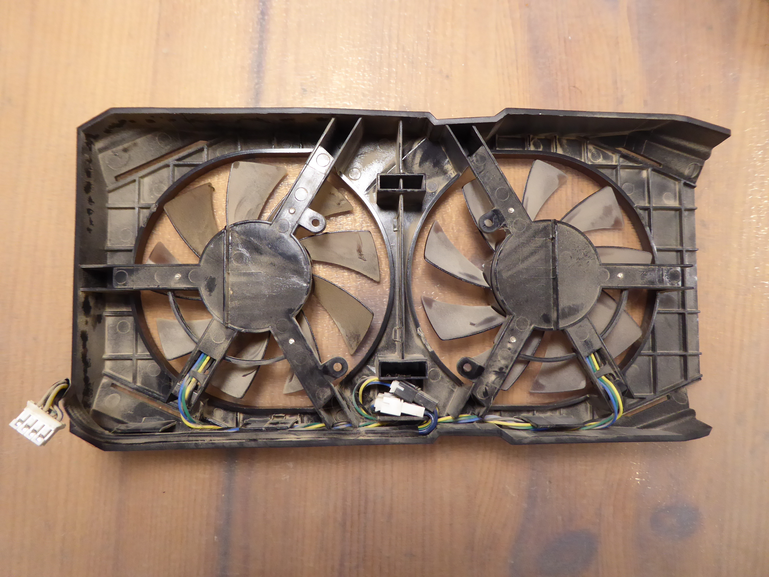
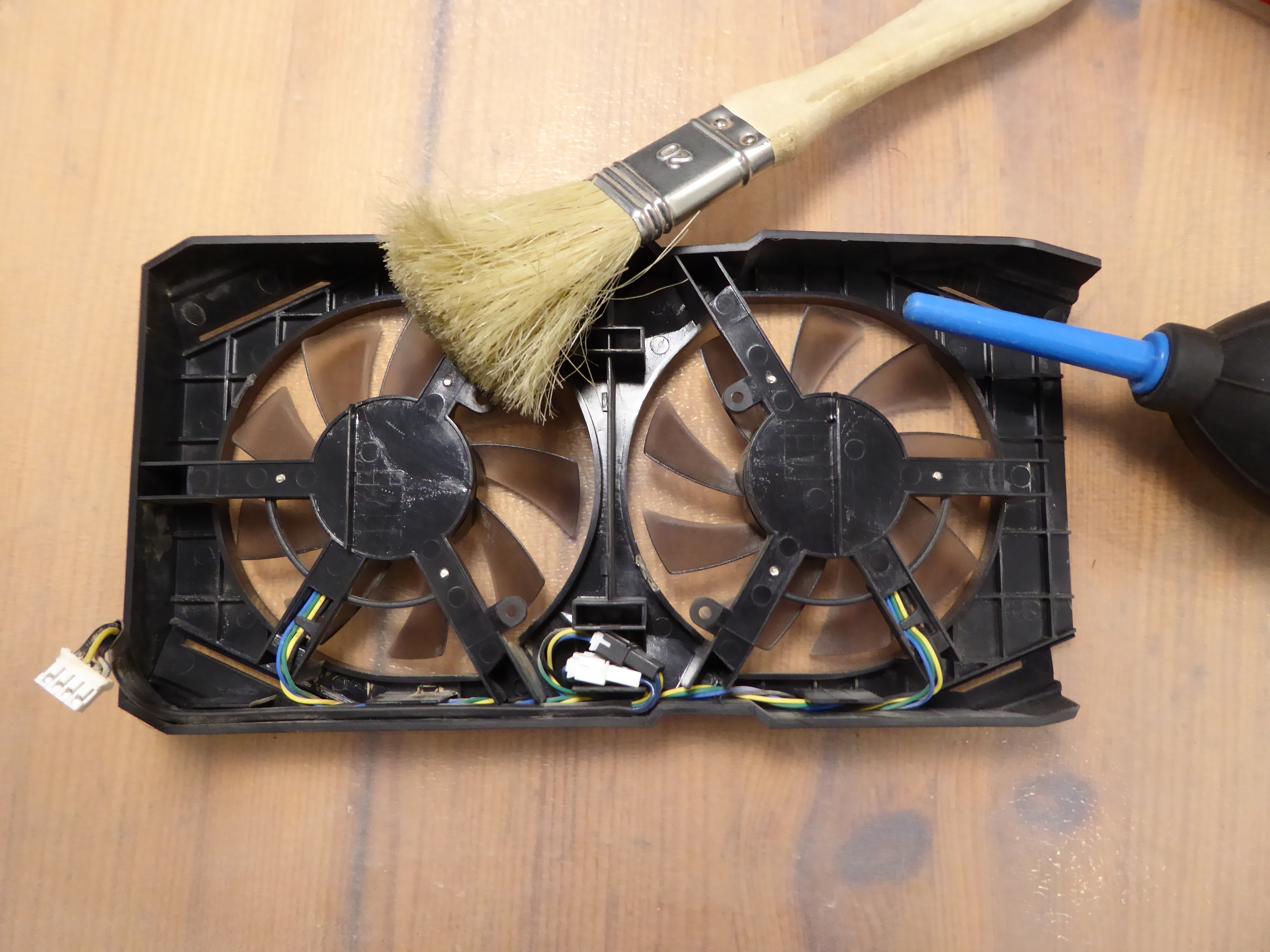
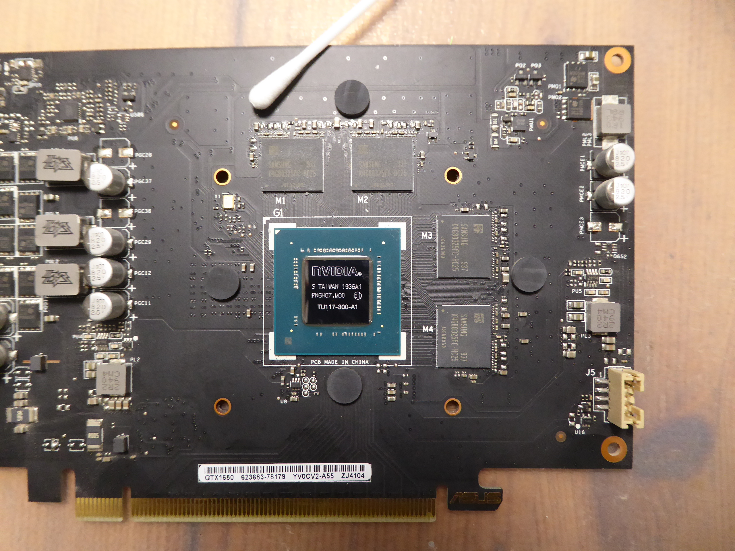
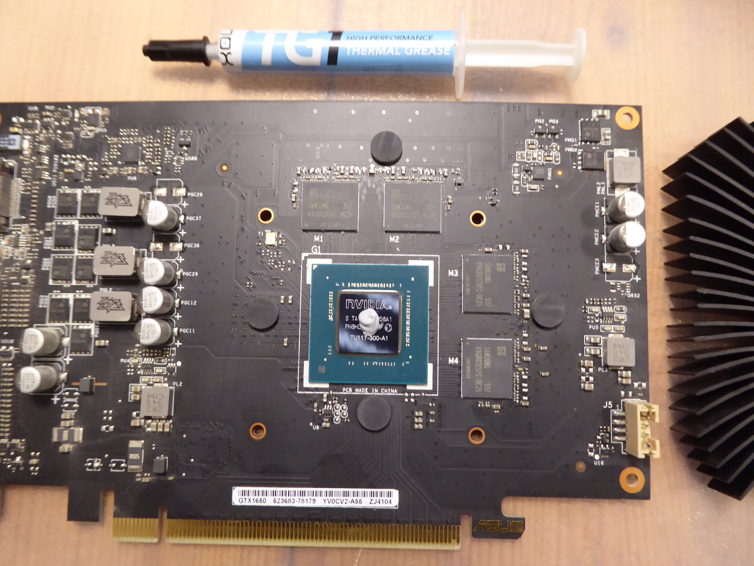
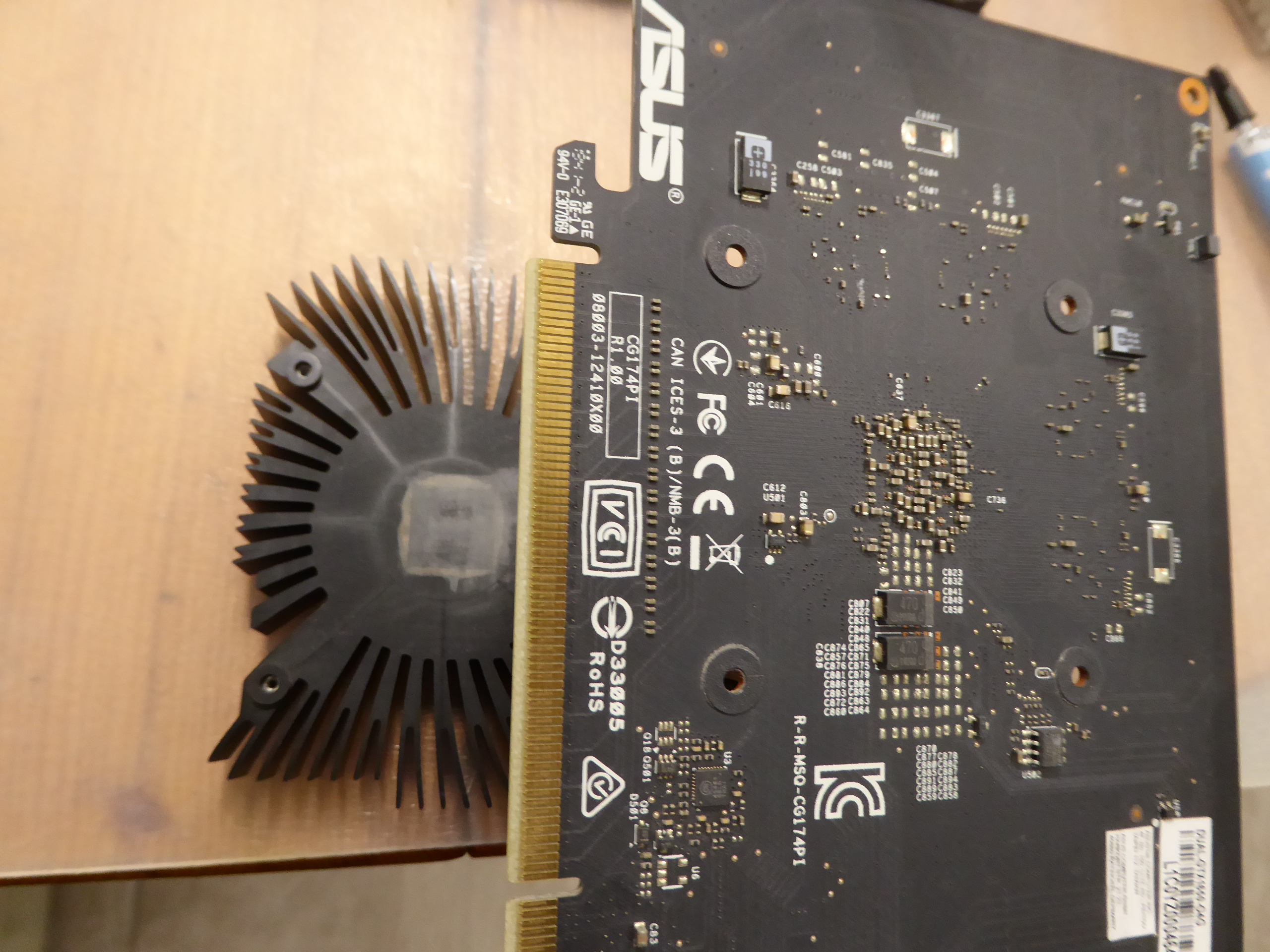
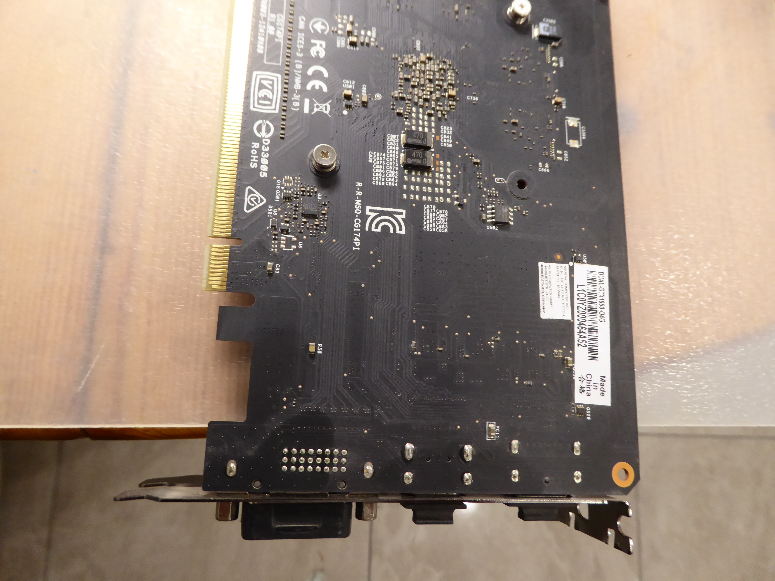
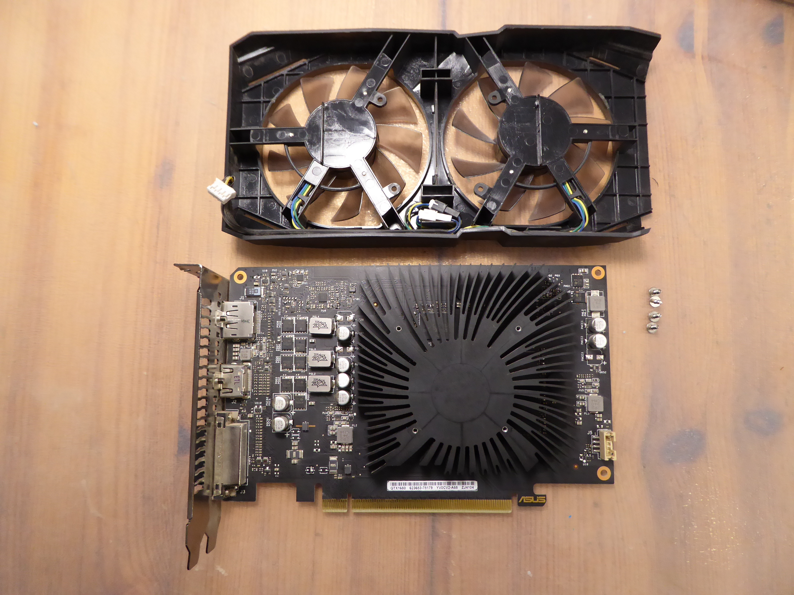
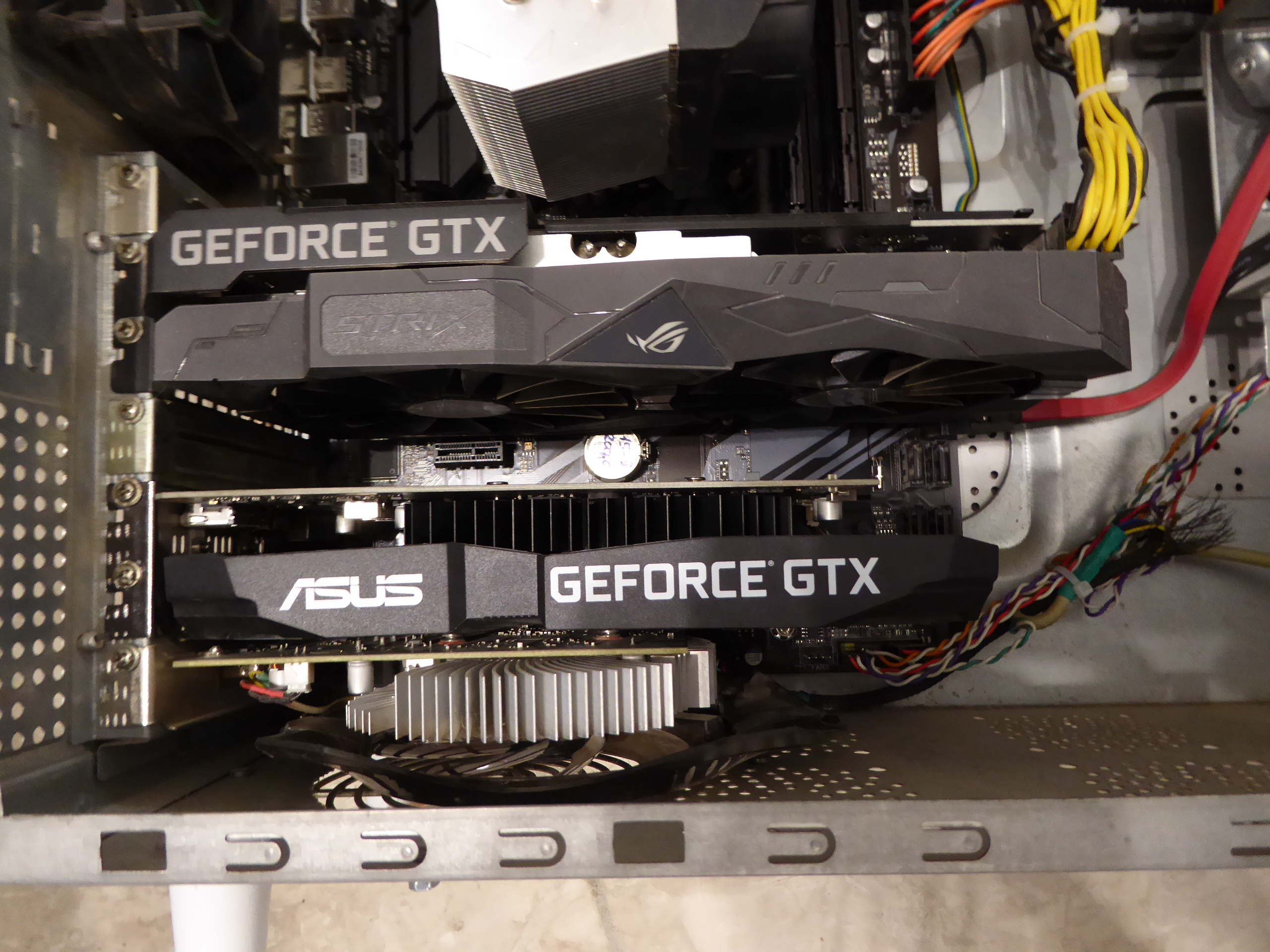
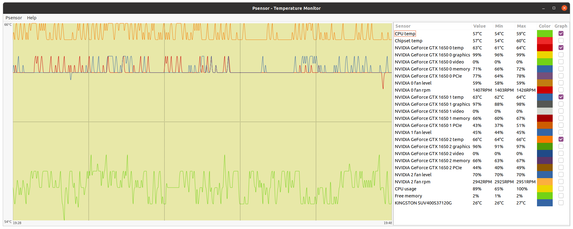
Graphics card cleaning During a temperature survey, I noticed high values for one of the graphics cards on a triple GPU system. Psensor monitoring application refers to this graphics card as "NVIDIA GeForce GTX 1650 2" It is physically the middle one card on this 3x GTX 1650 blended GPU system, having the worst air circulation of them. Temperature for this card was hitting 81 ºC, and then stabilizing at 80 ºC. This is enough reason for me to discard some problem on its refrigeration system. Both fans are turning, no problem on them. A full maintenance consists of dismounting heatsink and fans, cleaning them and circuitry thoroughly, and replacing the thermal paste. Here is the affected graphics card on the table. This other image shows the heatsink and fans frame dismounted apart. I'm starting by cleaning the anodized aluminum heatsink with a rigid bristles brush. I usually remove any labels attached to fins, to improve air circulation as much as possible. I also removed any aged thermal paste leftovers by means of cotton swabs and alcohol. Here is the heatsink appearance before and after cleaning. Now is time for the fans frame. I'll use a soft bristles brush and optics blower for cleaning the whole assembly. Here is the fans frame before and after cleaning. And lastly, I'm cleaning the circuitry from stacked dust, and removing thermal paste leftovers from GPU chip and silicon. Here is its final look. Now is time to remount everything again, starting by dispensing some self-spreading thermal paste over GPU chip's silicon surface. My favorite way to remount heatsink is by lying it upwards on the border of the table, and then aproaching the graphics card circuitry while watching a perfect match by looking coincidence through card's fixing holes. Then I slightly attach screws on two corners, then on the other two, and fix them completely by turning gradually to the end, following a cross pattern. Now the graphics card is ready to attach the fans frame again (please, don't forget to reattach fan's electrical connector first ;-) Finally, graphics card is again at its working position. Currently, this graphics card is running slightly overclocked (+55 MHZ), with a fixed 70% fan rate to enhance air circulation. Enough to get 48H bonus, that it was missing earlier. Differences in working temperatures can be appreciated by comparing the before and after graphics. |
|
ServicEnginIC Send message Joined: 24 Sep 10 Posts: 595 Credit: 13,083,686,510 RAC: 745,928 Level Scientific publications |
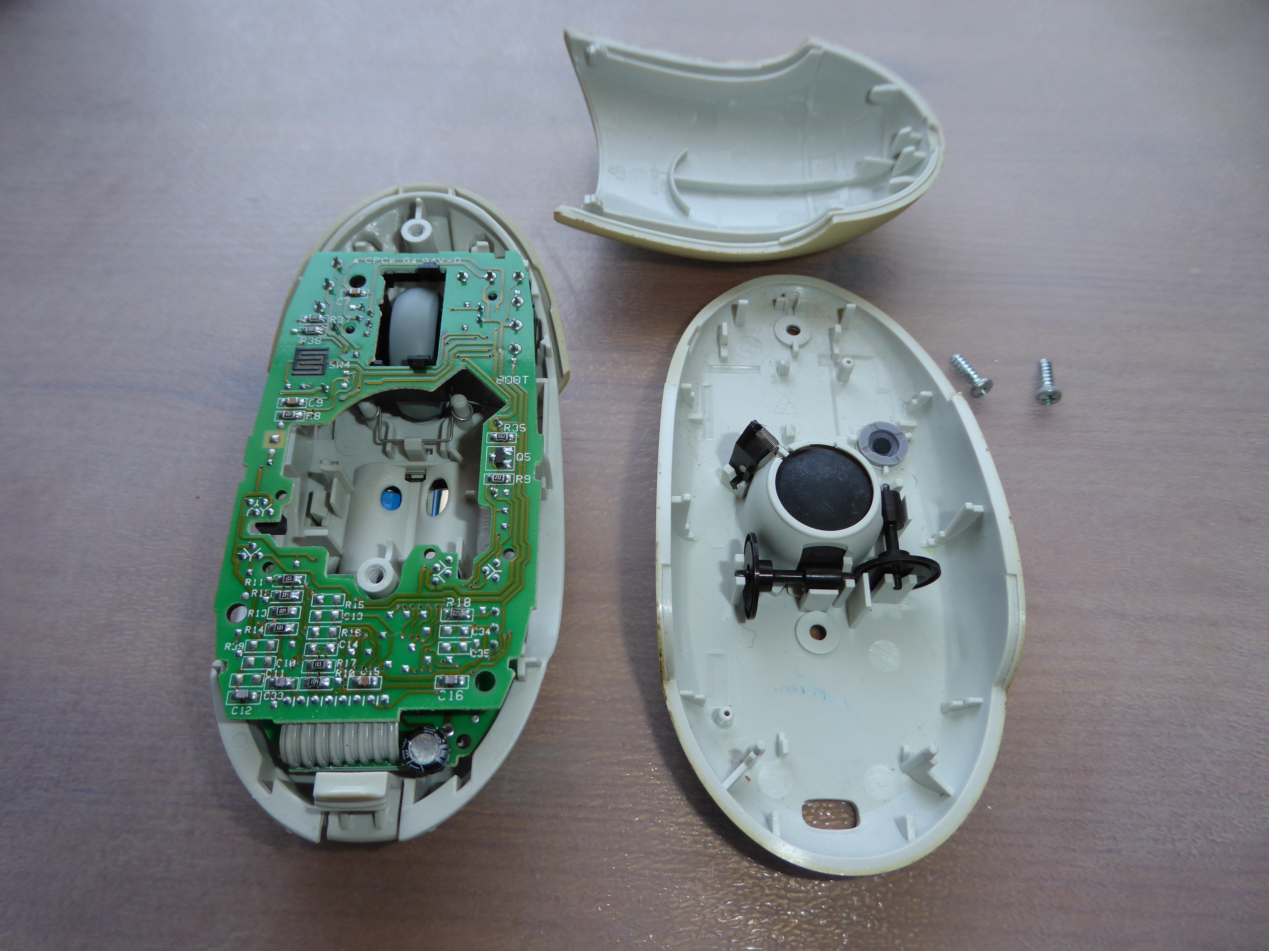
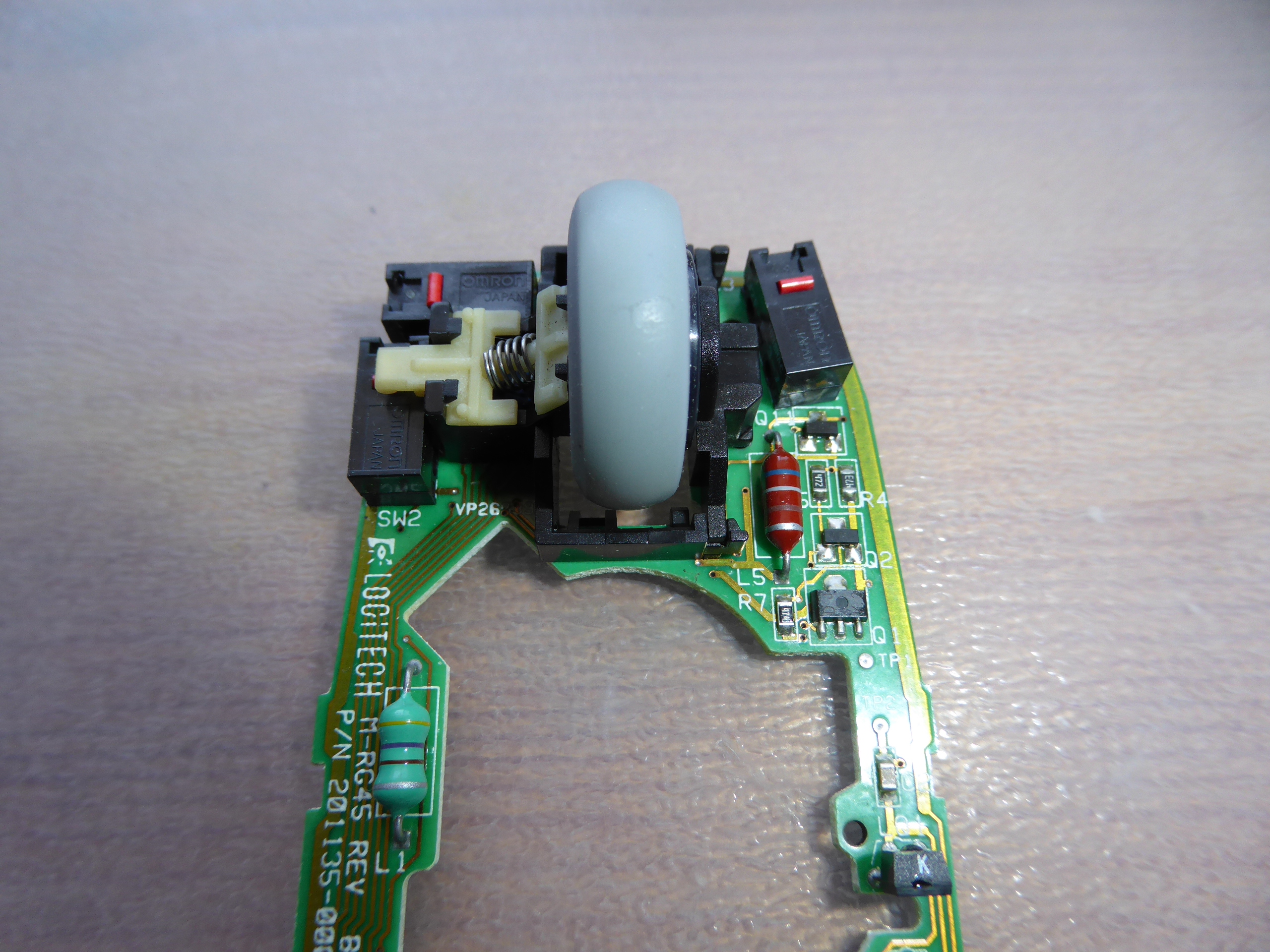
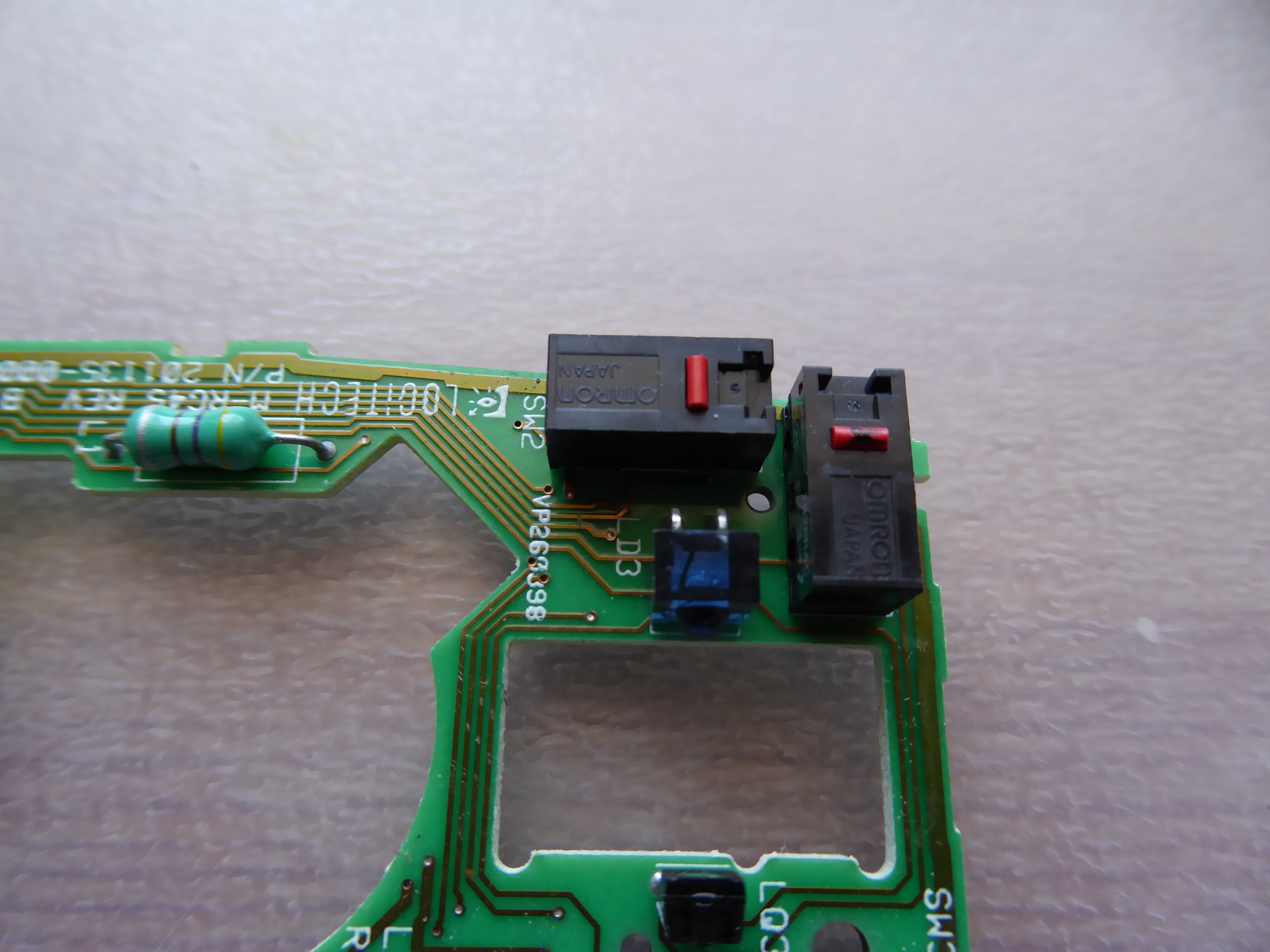
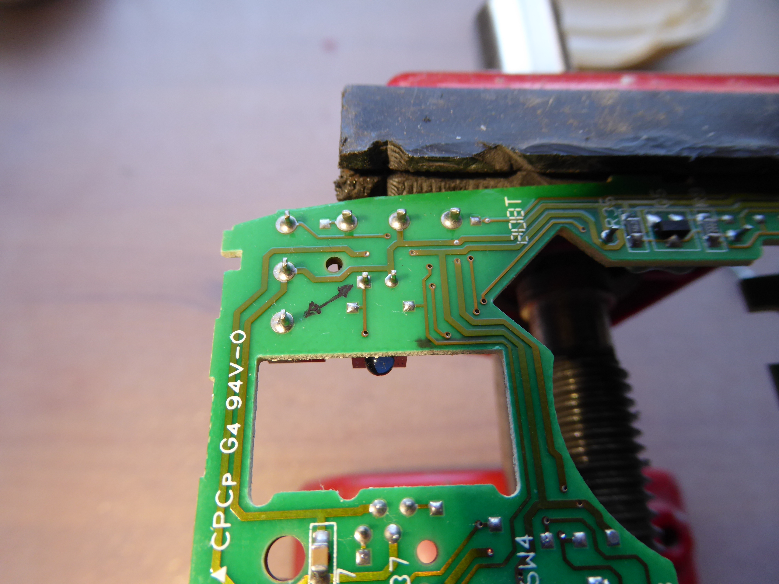
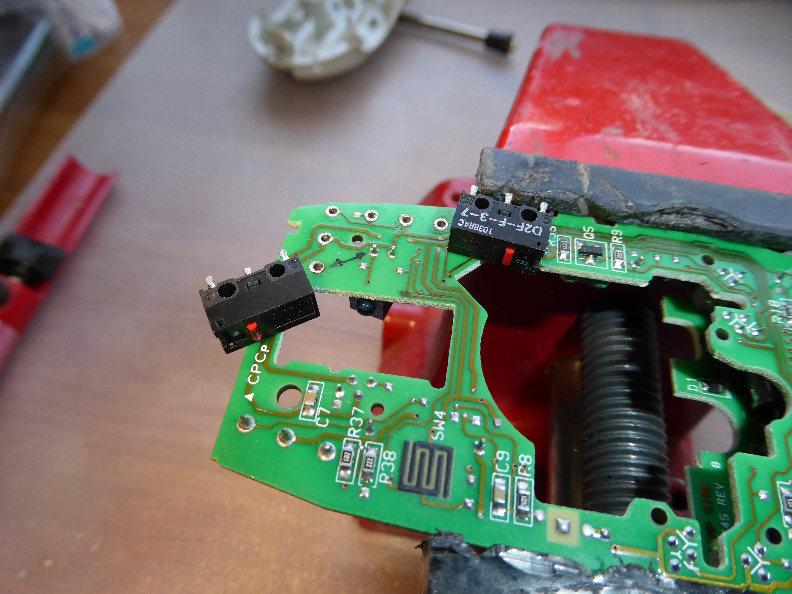
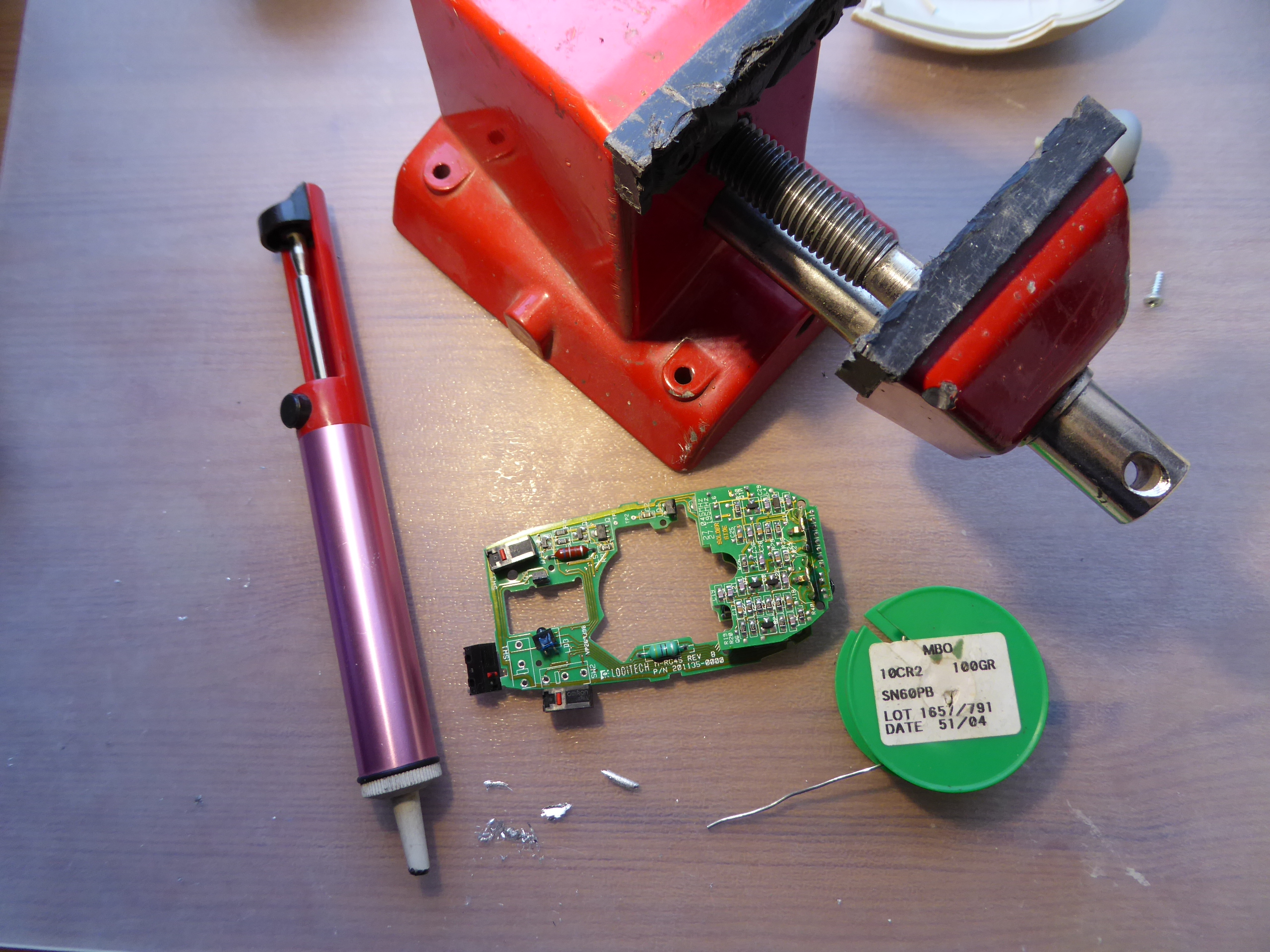
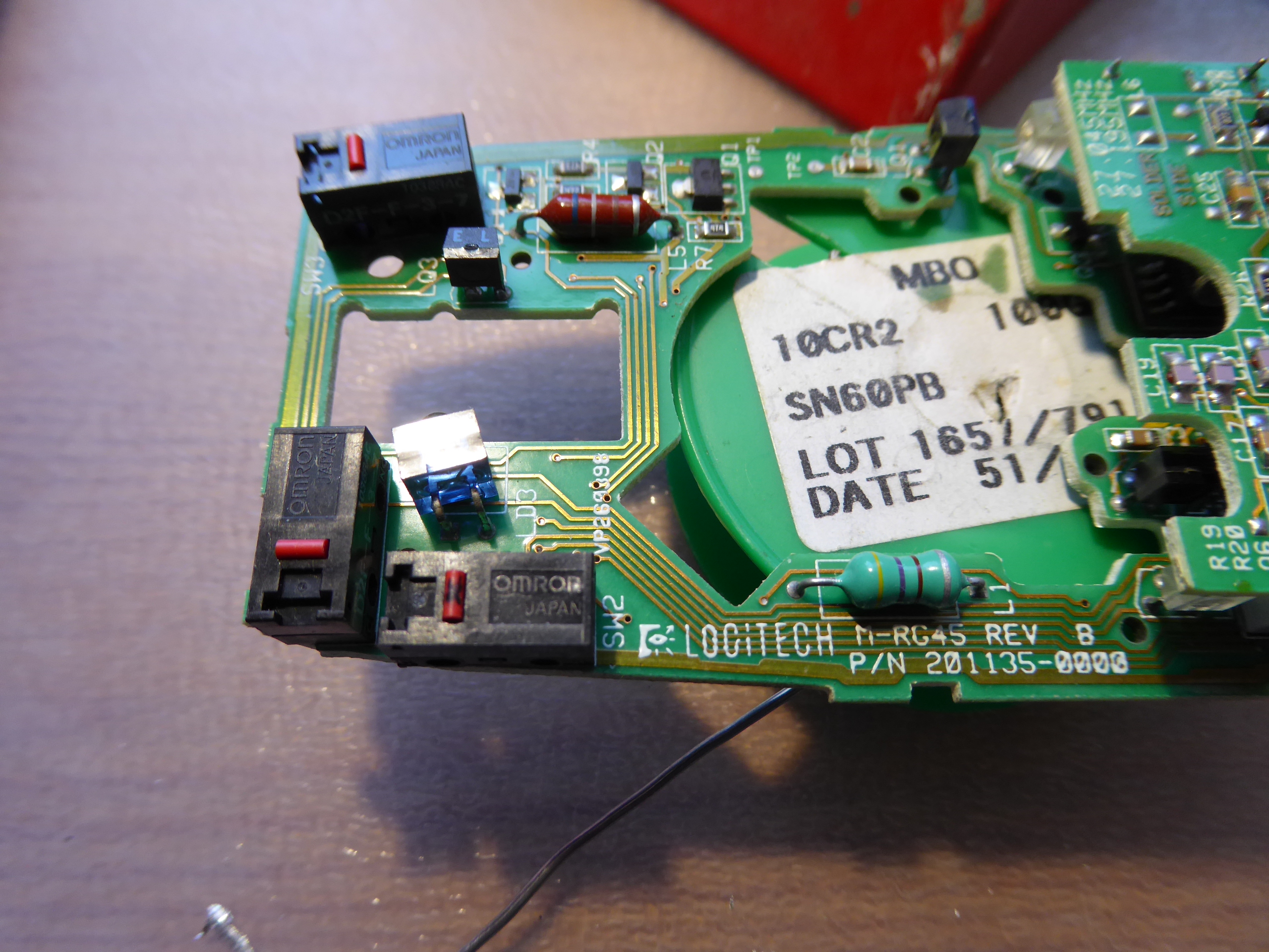
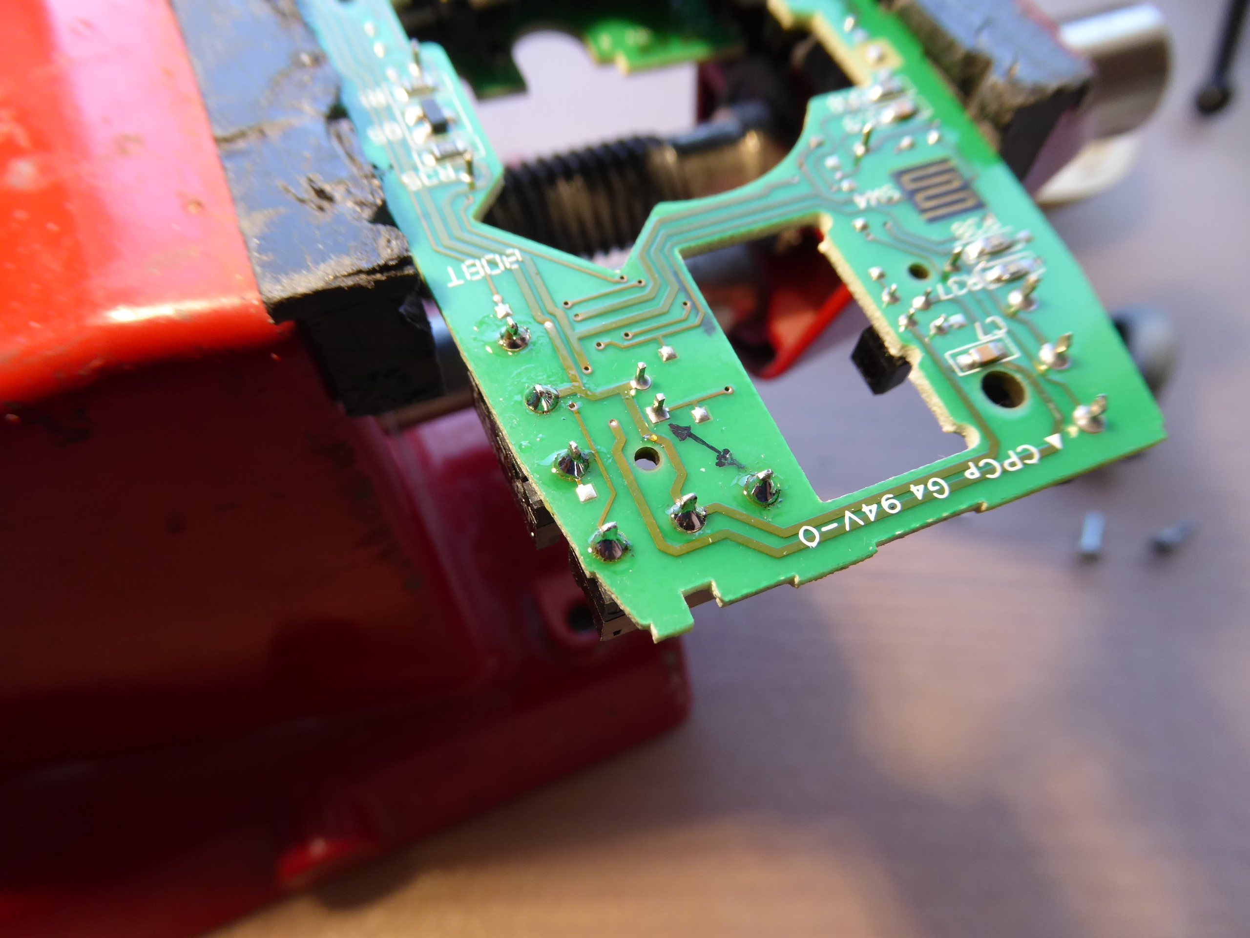
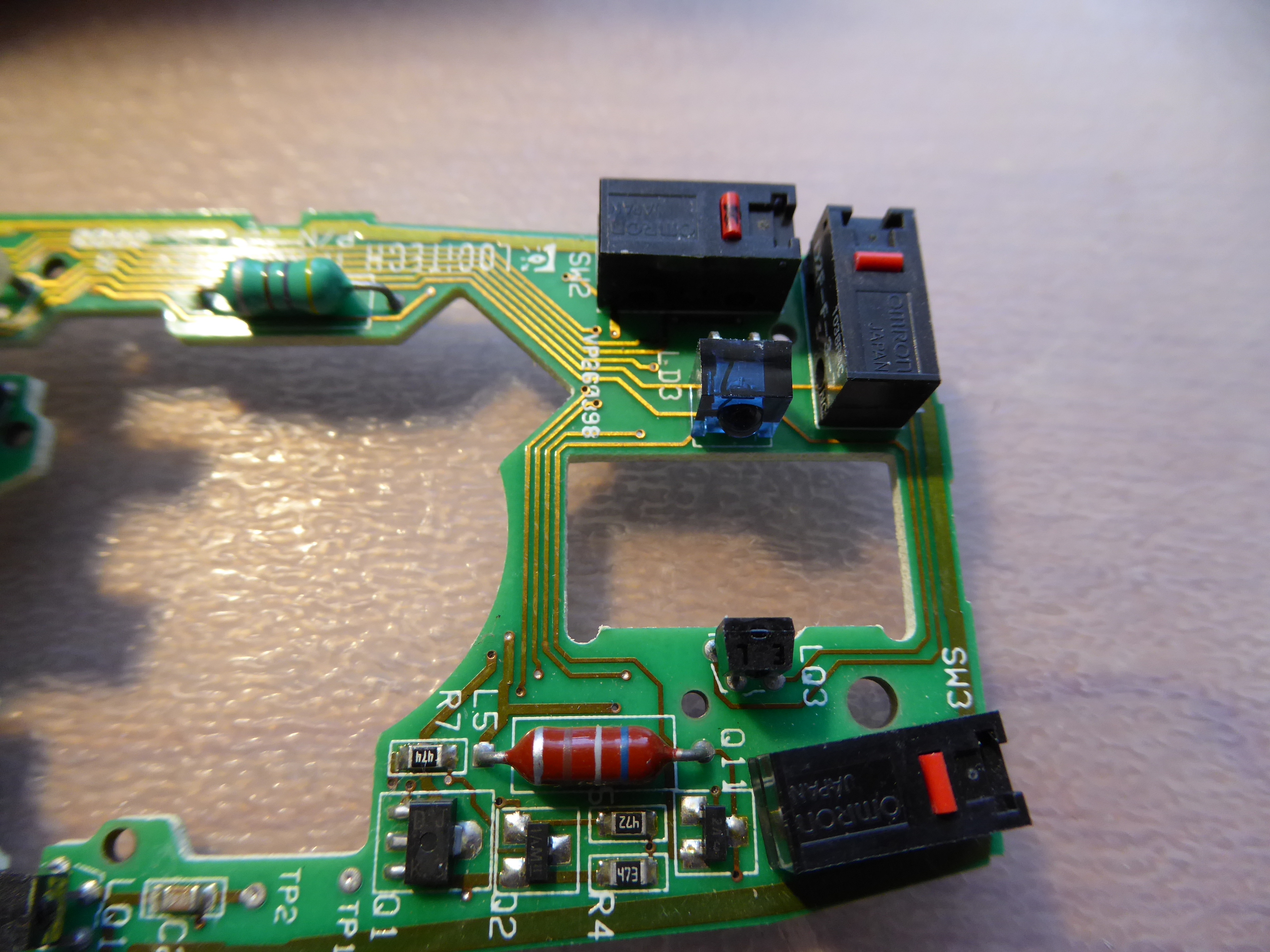
Desoldering - Soldering Practices 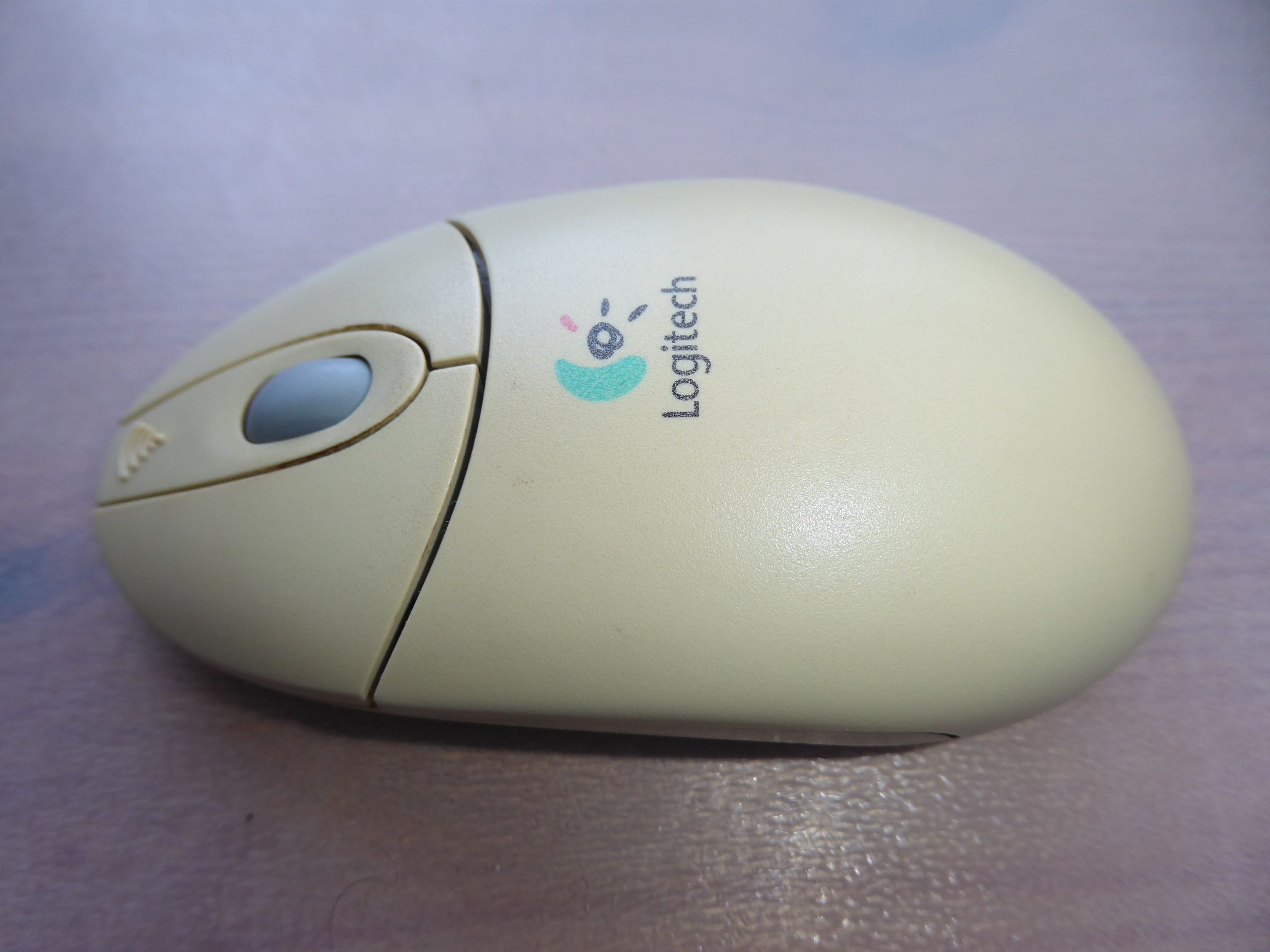 We're using this old wireless mouse to take a look to some electrical desoldering - soldering basics. It has a true problem: Left key switch activation has been getting harder and harder, making it uncomfortable for double click, or even for single click push. This mouse has three switches, being the central one in perfect condition and nearly unused in daily routine. The main objective is to see how to unsolder for swapping both switches and how to solder again. The secondary objective is to recover this mouse to a comfortable use, instead of discarding it. (Yes, I'm a hard recycler, you know ;-) And a tertiary goal would be to encourage someone to take his/her own desoldering - soldering practices. Will you? Any electronics scrap would be useful as practicing material... Let's start... Ooops! Two philips screws removed, and we have the mouse torn apart into pieces. Here we have a close look of the main circuit. The two microswitches for left and right keys are clearly visible, and the third one is partially hidden under the wheel mechanism. The wheel mechanism is esasily removed by grasping two plastic tabs, and we have at sight the two implied microswitches. I've marked the defective left key microswitch with a black dot, for not giving any chance to get confused with the good one after desoldering both. For a better handling while desoldering, I've held the circuit at a holding clamp. Now we are desoldering the three electrical terminals for both microswitches. Several tips here to take in mind: - Be patient to wait for the soldering iron to reach its right working temperature. If it is not hot enough, soldering tin will not get completely fluid. - I'm using a desoldering pump. Charge the desoldering pump plunger by pressing it to its latching position. - Heat each terminal until the soldering tin is molten, testing it by pushing the terminal and checking that it tilts. But not for too long: the microswitches have a plastic body that would melt if averheated. - Bring the desoldering pump nozzle as close as possible to the soldering point, separate the soldering iron tip, and immediately press the desoldering pump aspirating button. These operations can be seen in sequence at the following video:  After desoldering the terminals, push them gently to check that they are moving free on its mounting hole at printed circuit board (PCB). It can be seen at the following video: 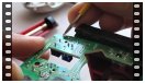 If any of them doesn't get free, it is usually better to re-solder with fresh soldering tin, and then desoldering again. When every terminals are free, it will be possible to extract the microswitch by pulling it and tilting with a zigzag movement, as shown at this video: 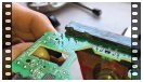 Following the related procedure, both microswitches are released now. At this other image can be seen the employed desoldering pump, the mouse PCB, the holding clamp, the soldering tin reel, and soldering tin leftovers from desoldering. Now we have swapped the two microswitches, and both are inserted at their new locations, ready for soldering. Several other tips: - I'm temporary fixing the microswitch central terminal by means of a small amount of fresh soldering tin, while pushing it at its final position. - I'm soldering definitely the other two terminals, melting fresh soldering tin at each terminal base, then ending with an ascending movement of the soldering iron tip along the terminal. I'm being brief in that operations, for not heating the terminals too much. Otherwise, microswitch plastic body might overheat and deform. - Then, I'm soldering definitely the central terminal the same way. All these steps can be seen at the next video: 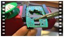 Here are the finished electrical connections after soldering. And here is the final look of mouse PCB after swapping micrositches. It's moment for re-mounting and testing: Ok!  And finally, a listing image of the employed material, hoping you have enjoyed it as I did 🤗️ 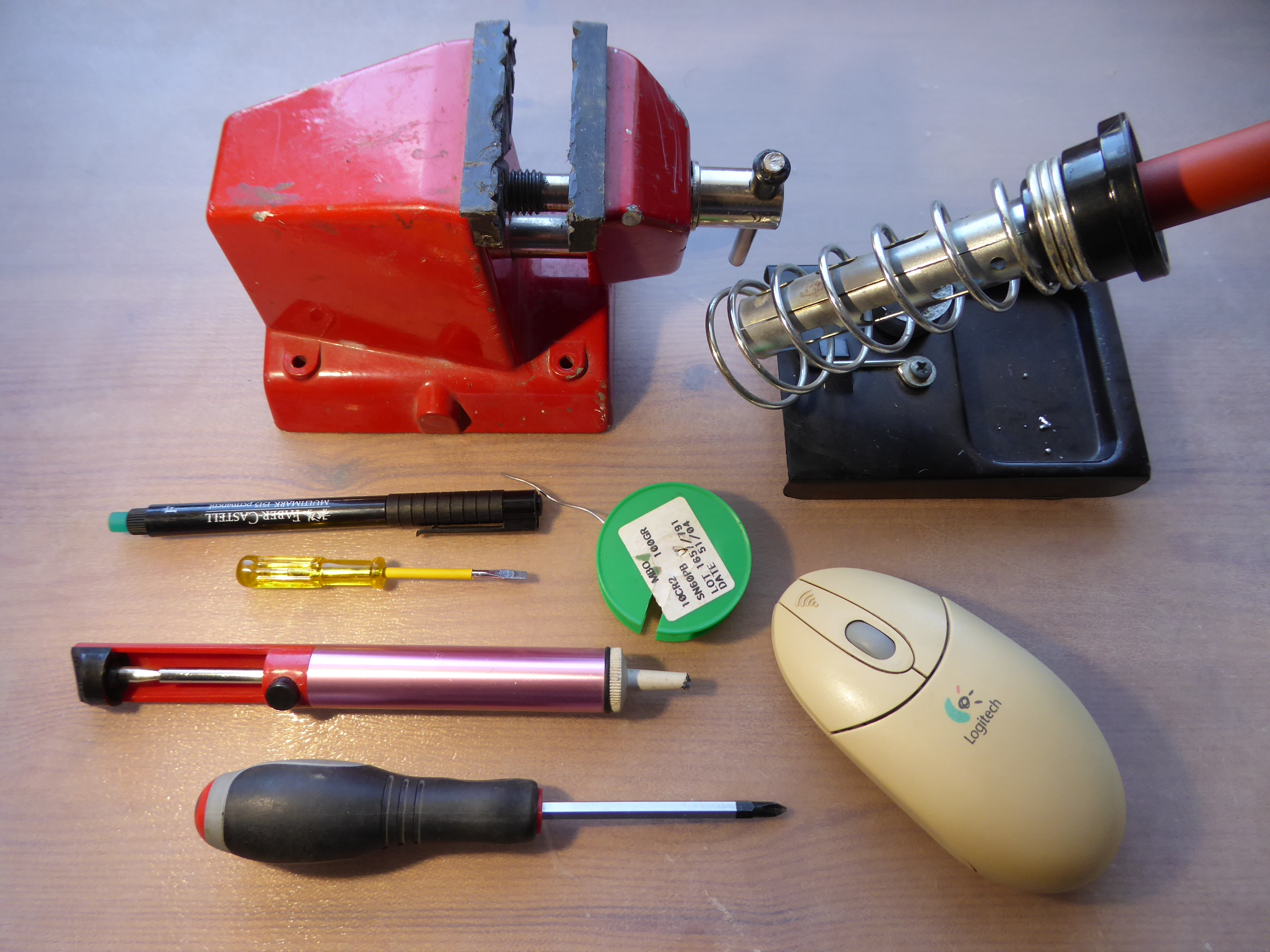 |
|
ServicEnginIC Send message Joined: 24 Sep 10 Posts: 595 Credit: 13,083,686,510 RAC: 745,928 Level Scientific publications |
Well... I'm still learning about publishing contents 😊 Excuse me for repeating the same previous post, this time the videos are re-coded for a better compatibility with more platforms (I hope) After trying several combinations, I found the best compatibility in .mp4 format, x264 video codec. Utility used for re-code: Any Video Converter Desoldering - Soldering Practices We're using this old wireless mouse to take a look to some electrical desoldering - soldering basics. It has a true problem: Left key switch activation has been getting harder and harder, making it uncomfortable for double click, or even for single click push. This mouse has three switches, being the central one in perfect condition and nearly unused in daily routine. The main objective is to see how to unsolder for swapping both switches and how to solder again. The secondary objective is to recover this mouse to a comfortable use, instead of discarding it. (Yes, I'm a hard recycler, you know ;-) And a tertiary goal would be to encourage someone to take his/her own desoldering - soldering practices. Will you? Any electronics scrap would be useful as practicing material... Let's start... Ooops! Two philips screws removed, and we have the mouse torn apart into pieces. Here we have a close look of the main circuit. The two microswitches for left and right keys are clearly visible, and the third one is partially hidden under the wheel mechanism. The wheel mechanism is esasily removed by grasping two plastic tabs, and we have at sight the two implied microswitches. I've marked the defective left key microswitch with a black dot, for not giving any chance to get confused with the good one after desoldering both. For a better handling while desoldering, I've held the circuit at a holding clamp. Now we are desoldering the three electrical terminals for both microswitches. Several tips here to take in mind: - Be patient to wait for the soldering iron to reach its right working temperature. If it is not hot enough, soldering tin will not get completely fluid. - I'm using a desoldering pump. Charge the desoldering pump plunger by pressing it to its latching position. - Heat each terminal until the soldering tin is molten, testing it by pushing the terminal and checking that it tilts. But not for too long: the microswitches have a plastic body that would melt if averheated. - Bring the desoldering pump nozzle as close as possible to the soldering point, separate the soldering iron tip, and immediately press the desoldering pump aspirating button. These operations can be seen in sequence at the following video: After desoldering the terminals, push them gently to check that they are moving free on its mounting hole at printed circuit board (PCB). It can be seen at the following video: If any of them doesn't get free, it is usually better to re-solder with fresh soldering tin, and then desoldering again. When every terminals are free, it will be possible to extract the microswitch by pulling it and tilting with a zigzag movement, as shown at this video: Following the related procedure, both microswitches are released now. At this other image can be seen the employed desoldering pump, the mouse PCB, the holding clamp, the soldering tin reel, and soldering tin leftovers from desoldering. Now we have swapped the two microswitches, and both are inserted at their new locations, ready for soldering. Several other tips: - I'm temporary fixing the microswitch central terminal by means of a small amount of fresh soldering tin, while pushing it at its final position. - I'm soldering definitely the other two terminals, melting fresh soldering tin at each terminal base, then ending with an ascending movement of the soldering iron tip along the terminal. I'm being brief in that operations, for not heating the terminals too much. Otherwise, microswitch plastic body might overheat and deform. - Then, I'm soldering definitely the central terminal the same way. All these steps can be seen at the next video: Here are the finished electrical connections after soldering. And here is the final look of mouse PCB after swapping micrositches. It's moment for re-mounting and testing: Ok! And finally, a listing image of the employed material, hoping you have enjoyed it as I did 🤗️ |
|
Send message Joined: 8 Aug 19 Posts: 252 Credit: 458,054,251 RAC: 0 Level Scientific publications |
I find that Noctua and Be-Quiet fans are excellent in my rigs on all three aspects of fan performance- lifespan, CFM/watt and noise rating. Neither manufacturer uses anything but the latest bearing types. They are a bit more expensive, but you get what you pay for. I'm sure there are other brands that are as highly recommendable also in that same price range. Just my take. "Together we crunch To check out a hunch And wish all our credit Could just buy us lunch" Piasa Tribe - Illini Nation |
|
Retvari Zoltan Send message Joined: 20 Jan 09 Posts: 2380 Credit: 16,897,957,044 RAC: 0 Level Scientific publications |
|
|
Send message Joined: 22 May 20 Posts: 110 Credit: 115,525,136 RAC: 0 Level Scientific publications |
I second that! They offer great value and especially their 3 and 5 fan boxes (depending on availability and where you live) are a great deal. They can be a little bit more cumbersome to clean though. I've got mine (P14 PWM) in a set of 5 for as little as 25€ last year and that is only ~ 1 or 2 Noctua fans. Arctic does also offer a new series called Bionix and I find that especially their Bionix F140 PWM fans are very powerful exhaust fans and still run quietly albeit notable. At a rated 104 CFM/ 176 m³/h they do move quite some air. Their "Co"- branded fan series (short for continuous) come with a dual ball bearing that offers even quieter operation than their standard P-series. It should offer a longevity bonus but it is too soon for me to verify their claims based on my own just 2 years experience with them. |


©2026 Universitat Pompeu Fabra