The hardware enthusiast's corner
Message boards :
Number crunching :
The hardware enthusiast's corner
Message board moderation
Previous · 1 · 2 · 3 · 4 · 5 . . . 16 · Next
| Author | Message |
|---|---|
 ServicEnginIC ServicEnginICSend message Joined: 24 Sep 10 Posts: 595 Credit: 13,083,686,510 RAC: 31,373 Level Scientific publications |
When replacing modular PSUs: Good punctualization. Thank you very much again! If anybody thinking to replace a modular PSU and keep the old cables, Please, forget it. Always retire old cables and install the cable set coming with the new PSU. A good source of info about PSUs: I also take note of this interesting link. |
|
ServicEnginIC Send message Joined: 24 Sep 10 Posts: 595 Credit: 13,083,686,510 RAC: 31,373 Level Scientific publications |
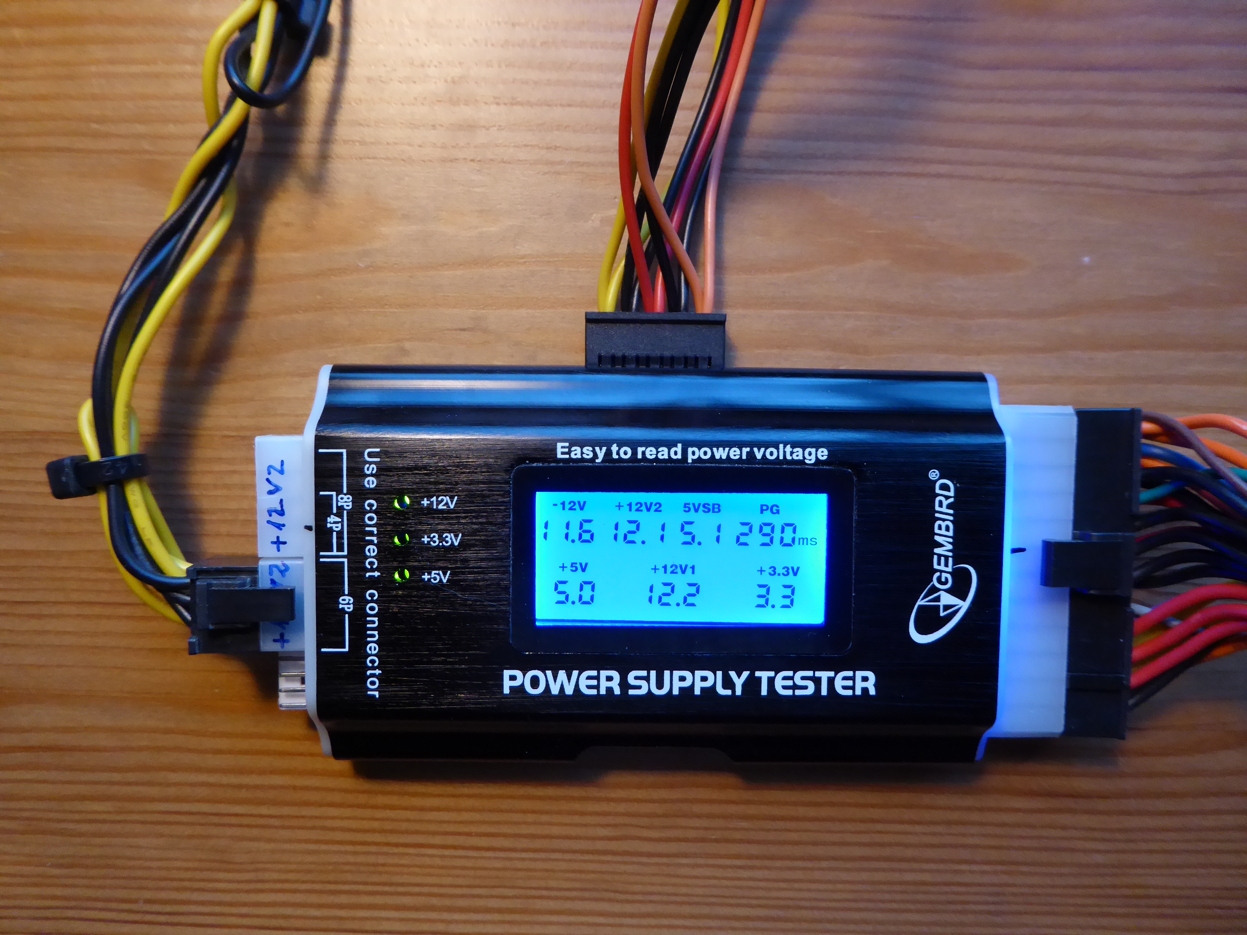
There are specific tools to easier diagnose PSUs, as the one shown below. PSU Tester To on-bench diagnose, it is enough to connect the 24 pin connector, one 4 or 6 or 8 pin connector, and one SATA connector. When switching PSU on, tester will automatically start it, and show the different voltages. Also delay between +12V on and 'Power Good' signal is shown. Abnormal voltages are those outside -5%...+5% for +12V, +5V, +3.3V and +5VSB. The -12V is more tolerant, and is considered normal in the range -10%...+10% Normal values for PG delay are in the range 200...500 ms - If PSU Doesn't start when switching on and correctly connected, probably it is dead and in the need to be replaced. - If any voltage is missing or outside tolerance, PSU needs to be replaced. VERY IMPORTANT If on-system PSU testing is made, it will be necessary to disconnect ALL PSU connectors from motherboard and peripherals. Please, double check this! As soon as this kind of test will bring power to every connectors, damage to system may occur if any of them is left connected. Althoug a faulty parameter indicates the need to replace the PSU, a passing PSU may be still defective. The reason: This kind of tests are made at very low currents compared to a system running at maximum performance. Running at higher currents may cause a parameter to fall ouside tolerance. Also some problems are caused by failing components when heating. And some intermitent problems might not be catched in such a brief test... |
|
Retvari Zoltan Send message Joined: 20 Jan 09 Posts: 2380 Credit: 16,897,957,044 RAC: 0 Level Scientific publications |
I have recently read about a special thermal "grease". It is actually a special metal compound which is liquid at room temperature like mercury (but it's not made of mercury). Its thermal conductivity is 6-10(!) times higher than of a usual thermal grease (73W/mK vs 8.5W/mK). See the manufacturer's page for reference: Thermal Grizzly Conductonaut I haven't tried it earlier, as it has a serious negative side: this metal compound (like most of the metals) conducts electricity as well as heat. So it must not get out of the chip's surface as it will result in a short circuit which breaks the GPU or the CPU (or the MB) for good. It should not be applied to aluminum heatsinks. But if you are experienced, have the time and patience to thoroughly clean the surface of the heatsink and the chip (or the IHS) with alcohol (I had to even use polish paper on one of my heatsinks), and carefully apply as less of this thermal compound as possible (to avoid the excess metal go where it shouldn't) then you can have a try with this product. The result will worth the time and effort: On my single GPU systems I experience · 10-15°C (!) lower temperatures at the same fan speed. · 30-50% (!) lower fan speed at the same temperatures. The better the heatsink, the better the result. You can choose how to balance between these by your fan curve. The factory settings will result in slightly lower (3-5°C) temperatures at a much lower fan speed. Of course, it can be used to achieve better overclocking as well. Most of the Intel CPUs have normal thermal grease between the CPU chip and the IHS, so it must be replaced with this product to achieve better results. As this grease is under the IHS (the metal covering the chip to protect it), first you have to remove the IHS, which is glued to the PCB (the green area) which carries the chip. There are professional tools to do this without damaging the CPU. Hopefully I'll have mine next week, and I'll report the results then. |
|
Send message Joined: 26 Feb 14 Posts: 211 Credit: 4,496,324,562 RAC: 0 Level Scientific publications |
Been using it for about a year now Zoltan for some of my bigger machines with higher thread counts. Was recommended by one of my teammates and never thought about it again. Good information.  
|
|
ServicEnginIC Send message Joined: 24 Sep 10 Posts: 595 Credit: 13,083,686,510 RAC: 31,373 Level Scientific publications |
See the manufacturer's page for reference: Thank you for your post, Retvari Zoltan. Thermal conductivity specifications for Conductonaut are really impressive. In the other hand, as you remark, it is contraindicated in live circuits due to its electrical conductivity. Following image comes from a true thermal paste replacing operation in one of my graphics cards: 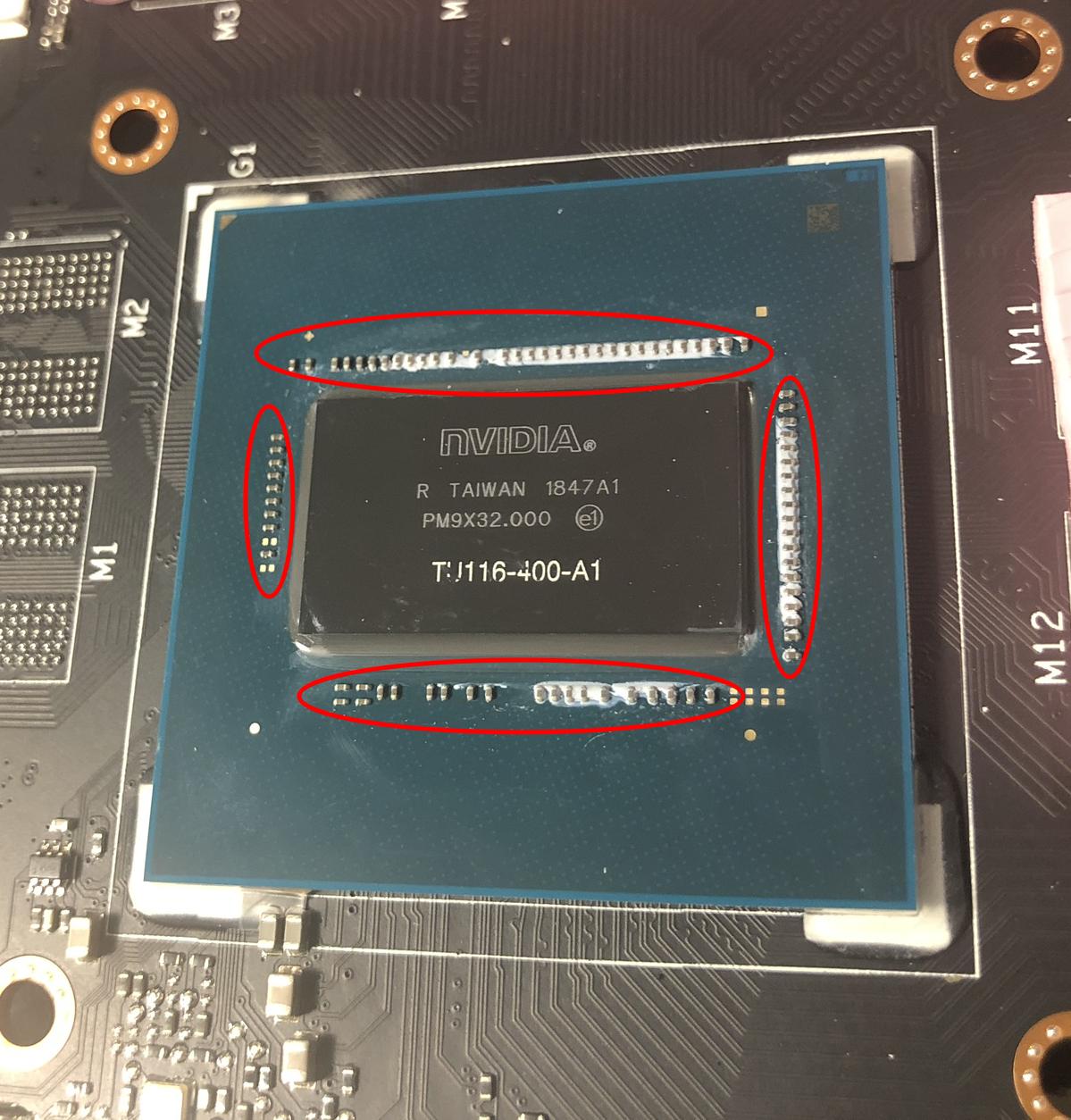 As seen in the image, GPU chip core usually is surrounded by capacitors (here remarked by red ellipses). That white compound between many of them is the reamining non-conductive factory thermal paste. Those capacitors would be shortcircuited if in contact with an electrically-conductive compound... Been using it for about a year now But used with due precautions where indicated, it's worth it. Thank you for your feedback, Zalster. I've navigated Thermal Grizzly products, and they have specific solutions for every use. I've got very well impressed by Kryonaut for general purpose applications. |
|
Retvari Zoltan Send message Joined: 20 Jan 09 Posts: 2380 Credit: 16,897,957,044 RAC: 0 Level Scientific publications |
Thermal conductivity specifications for Conductonaut are really impressive.I know. I was afraid of it too. But: The chip is much thicker than the conductors are. This metal compound acts like a fluid, while thermal grease acts like a grease. While it sounds more dangerous, you can apply it more precisely than a grease (you have to do it more carefully though). Conductonaut acts exactly like tin-lead alloy solder on a copper surface. If you ever soldered something to a large copper area of a PCB, you know how it works: the solder bonds to the copper surface, so if you don't use too much of it, it will stay there even if you try to shake it off. Liquid metal has very high surface tension, which holds it together (think of mercury). Because it can be (and it should be) applied in a very thin layer to the whole area of the chip, and to the chip's area on the heatsink, there won't be much excess material pushed out on the sides. The other reason for applying as less as possible that it's quite expensive. But if you want to be extra safe you can cover the capacitors with nail polish (or similar non conductive material) to protect them. |
|
Retvari Zoltan Send message Joined: 20 Jan 09 Posts: 2380 Credit: 16,897,957,044 RAC: 0 Level Scientific publications |
Another bit of advice for applying Conductonaut: It is better to apply it on the heatsink to a slightly larger area than the chip, because in this way the excess material will stick to the heatsink. This compound won't make the copper (silicon, nickel) surface wet by itself, you have to carefully rub it on both surfaces. This way it can be made really thin. You have to start with a very small (pinhead sized) droplet, and rub it on the desired area. If it turns out to be insufficient, you can add a little more (it won't make a droplet if you add it directly to the existing layer, it will add to the thickness of the layer instead). |
|
ServicEnginIC Send message Joined: 24 Sep 10 Posts: 595 Credit: 13,083,686,510 RAC: 31,373 Level Scientific publications |
Now I understand the mechanics for this product. I appreciate your masterclass very much. It is always a good time to learn something more! |
|
Retvari Zoltan Send message Joined: 20 Jan 09 Posts: 2380 Credit: 16,897,957,044 RAC: 0 Level Scientific publications |
On my single GPU systems I experienceIt's a little more complex than that: If you have a decent heatsink on your GPU (the GPU temperature is around 70°C), and the thermal paste is thin also it's in good condition, then the temperature decrease will be "only" around 5°C. Smaller chips with decent heatsink (for example GTX 1060 6G) will have only around 5°C decrease. Regardless of its material, good thermal paste is a thin thermal paste, so this way it can make a very thin layer between the chip and the cooler. You can check if your GPU needs a better thermal paste by watching its temperature when the GPUGrid client starts (on a cool GPU). If there's a sudden increase in the GPU temperature, then the thermal paste/grease is too thick, and/or it has become solid. The larger this sudden increase, the larger the benefit of changing the thermal interface material. Another experience I had after I changed the thermal paste (it's better to call it thermal concrete) to Conductonaut on my Gigabyte Aorus GTX 1080Ti 11G is that now it makes sense to raise the RPM of the cooling fans even to 100%: 55% 1583rpm: 69°C (original fan curve) 60% 1728rpm: 65°C 70% 2016rpm: 60°C 80% 2304rpm: 56°C 90% 2592rpm: 53°C 100% 2880rpm: 50°CThe noise of the fans is tolerable on 70%. Another idea on how to clean copper heatsinks: It's better to use scouring powder (with a little piece of wet paper towel) than polishing paper, because this way the tiny copper grains will stay on the heatsink (also it's easy to clean them off). The surface will be smoother (depending on the grit size of the polishing paper and the scouring powder). |
|
ServicEnginIC Send message Joined: 24 Sep 10 Posts: 595 Credit: 13,083,686,510 RAC: 31,373 Level Scientific publications |
I've ordered one 1g Conductonaut syringe, and I'm expecting to receive it in less than one month. I'm curious to test it and report results. |
|
ServicEnginIC Send message Joined: 24 Sep 10 Posts: 595 Credit: 13,083,686,510 RAC: 31,373 Level Scientific publications |
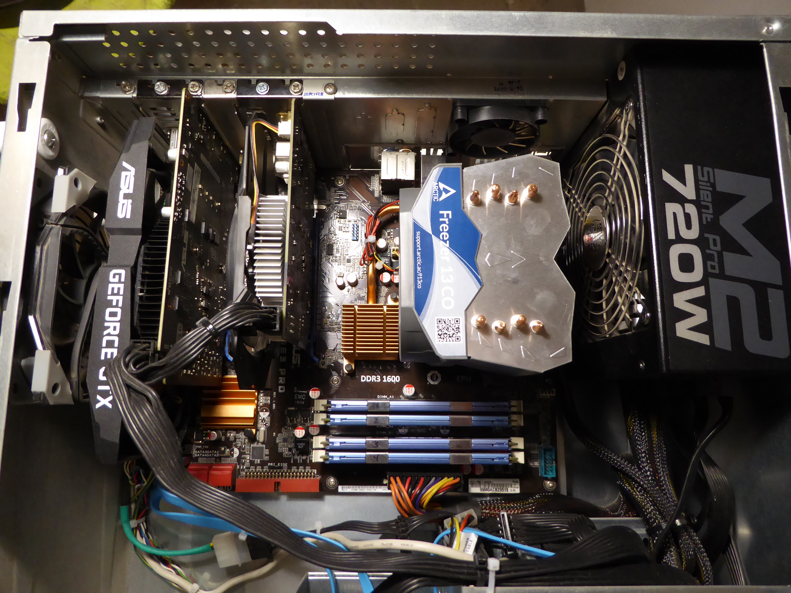
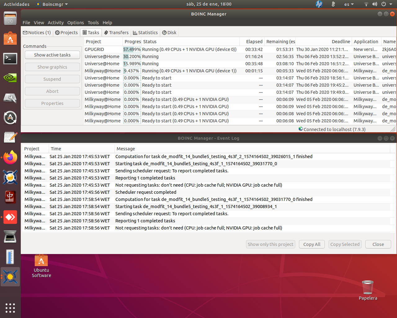
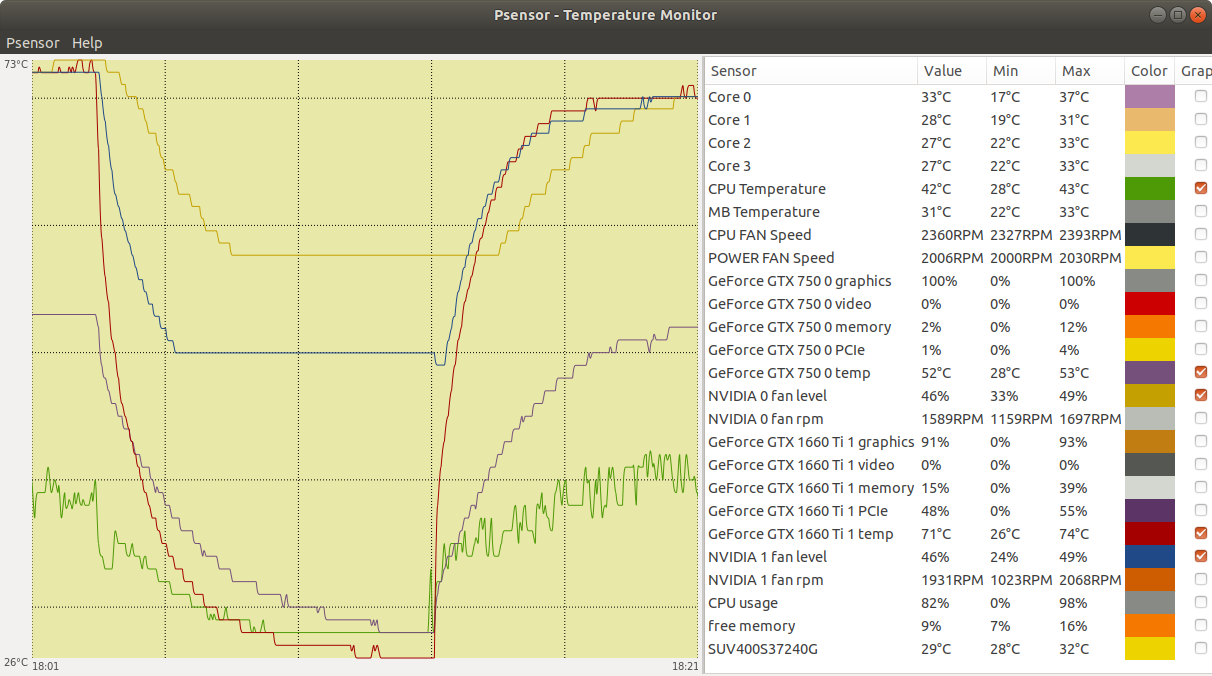
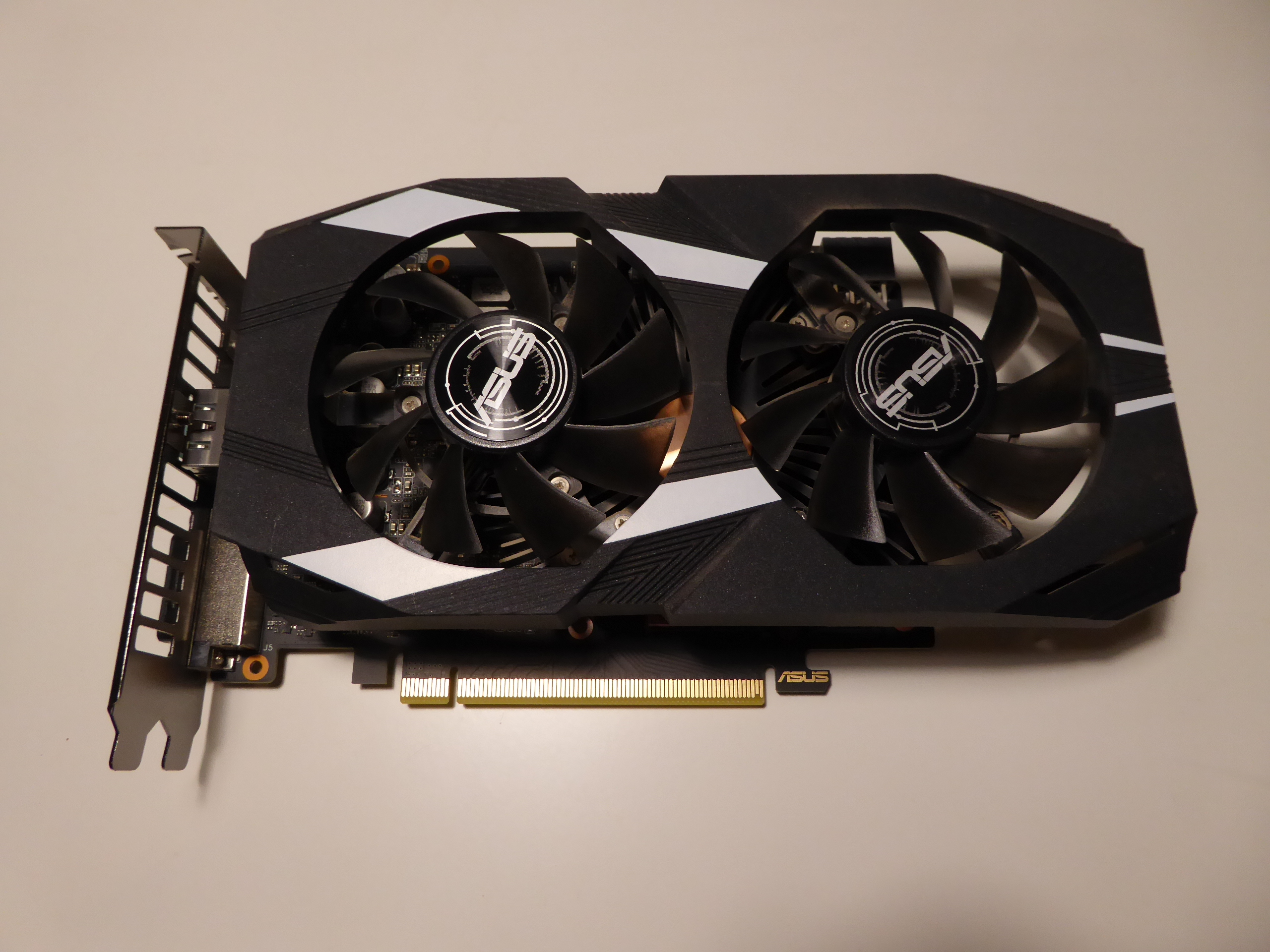
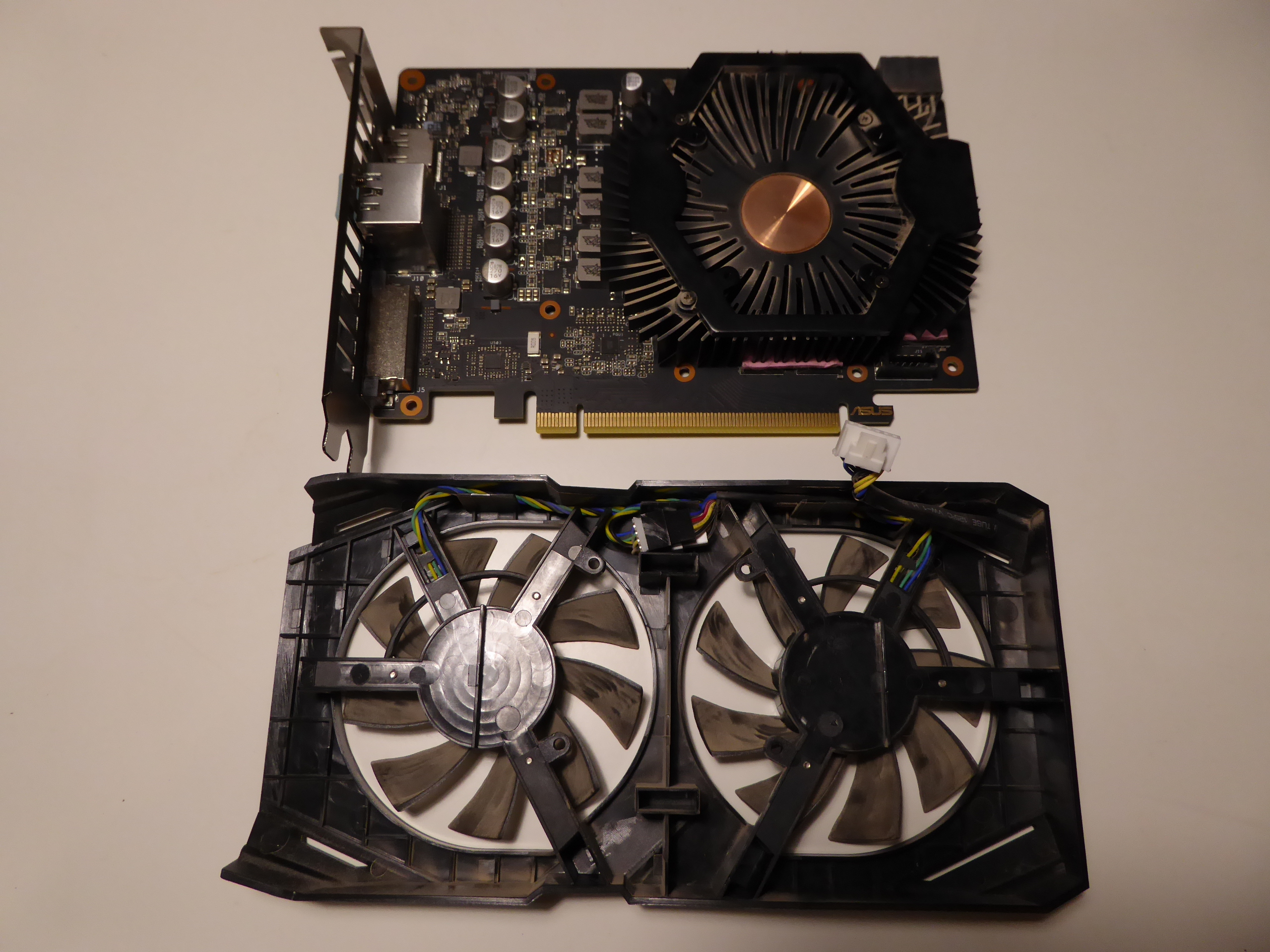
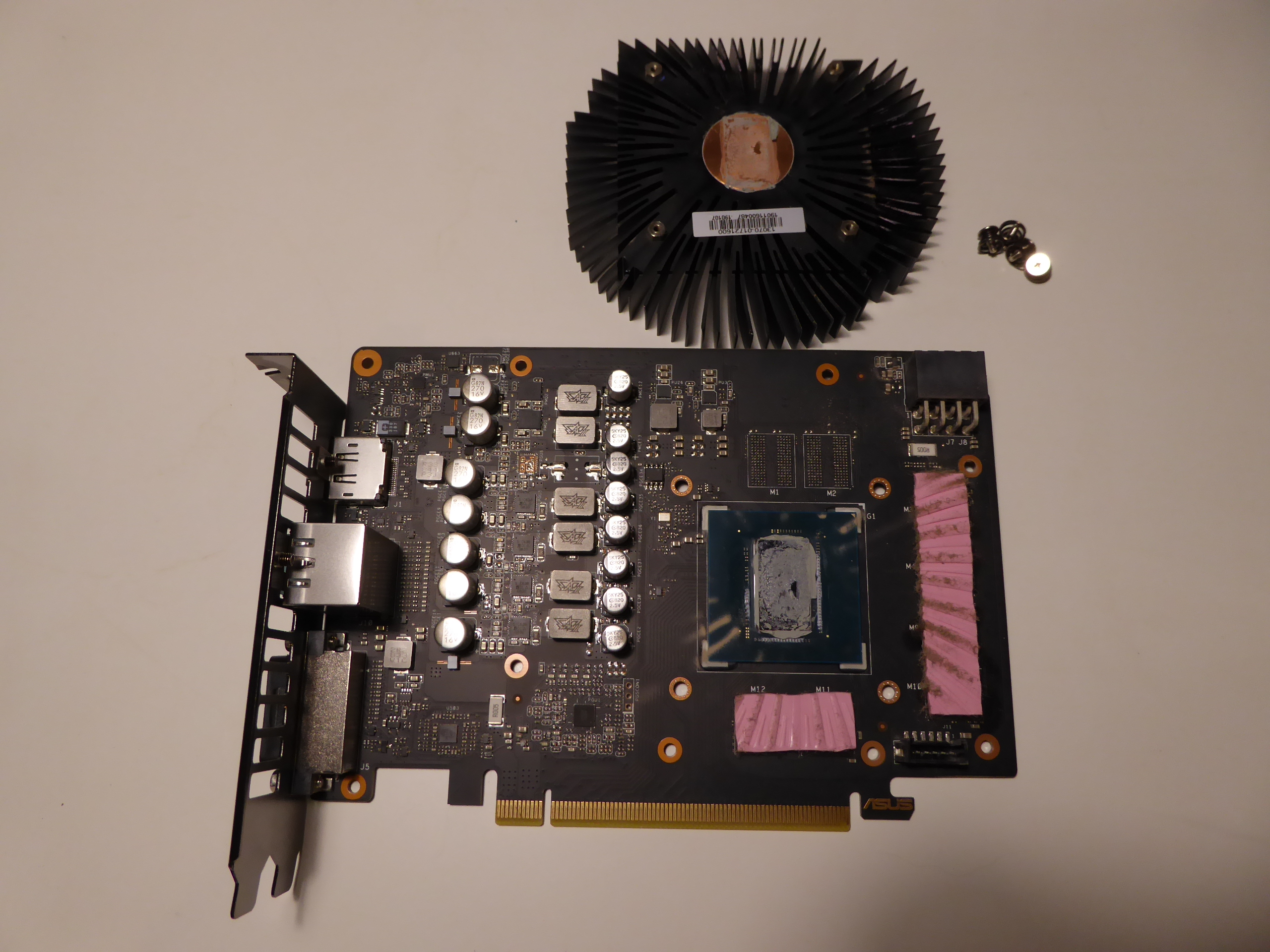
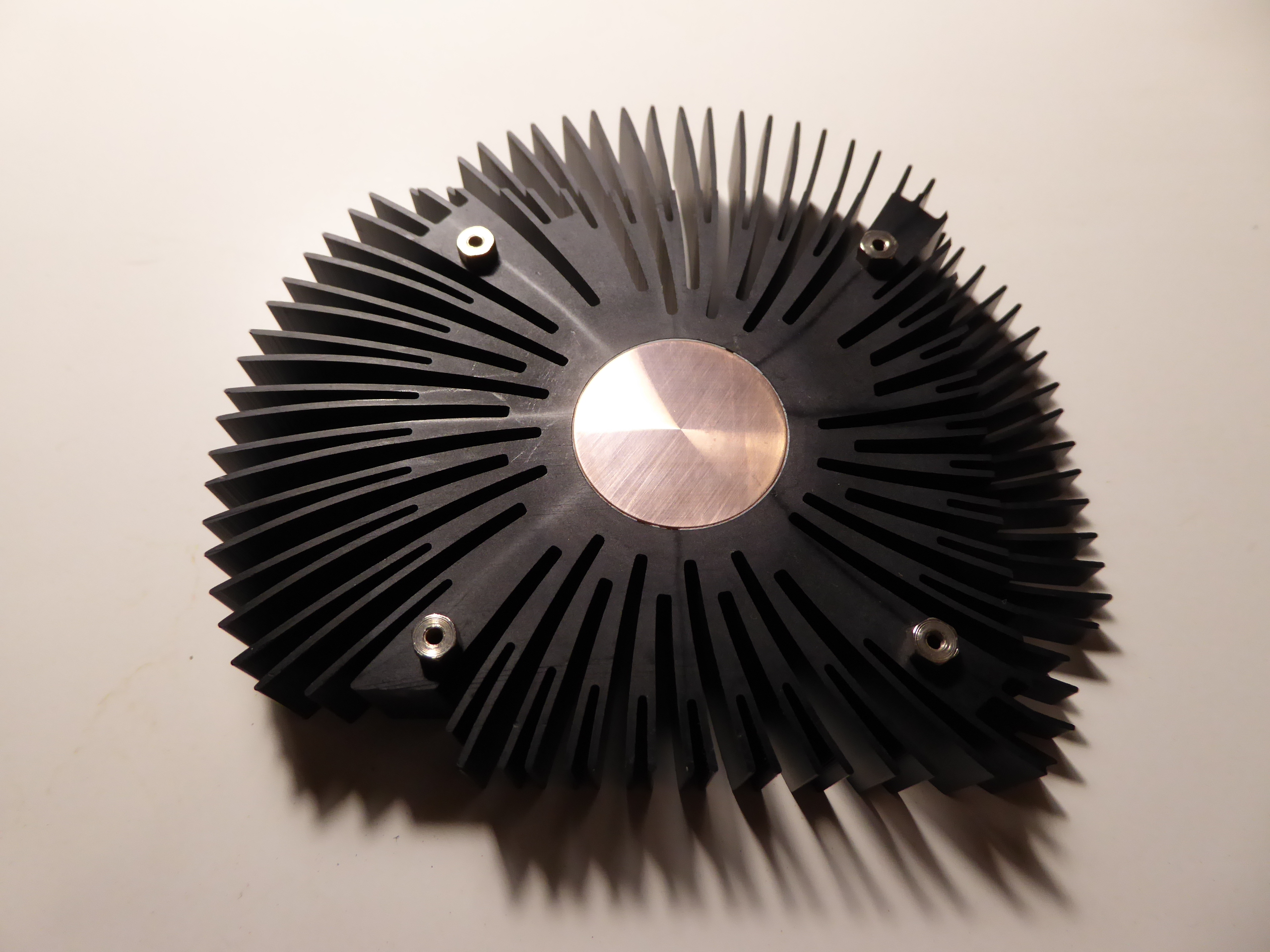
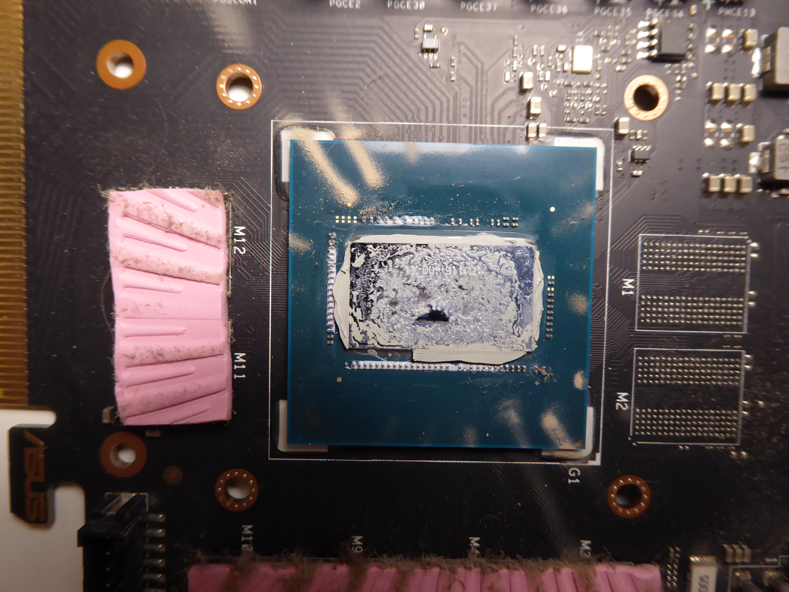
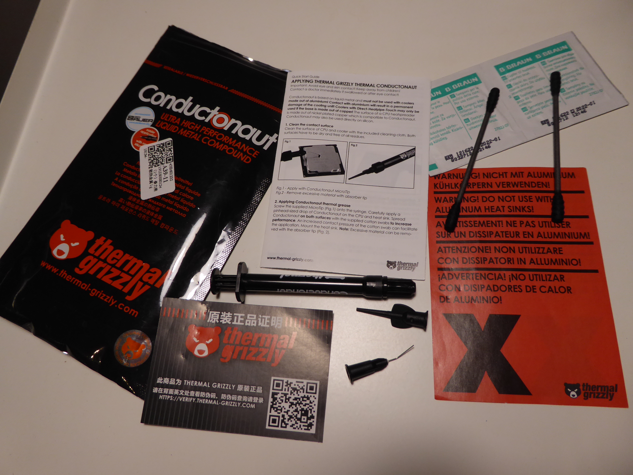
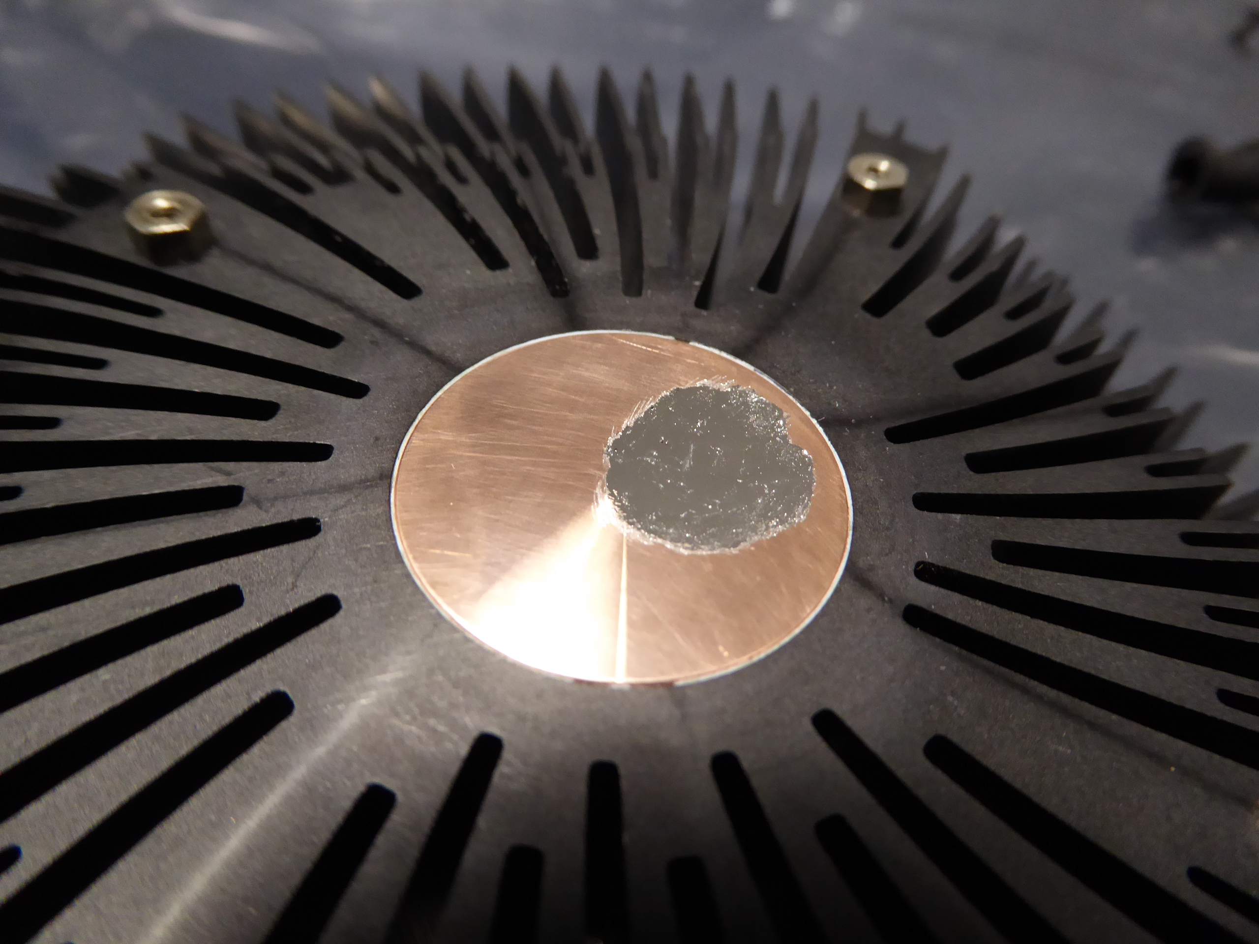
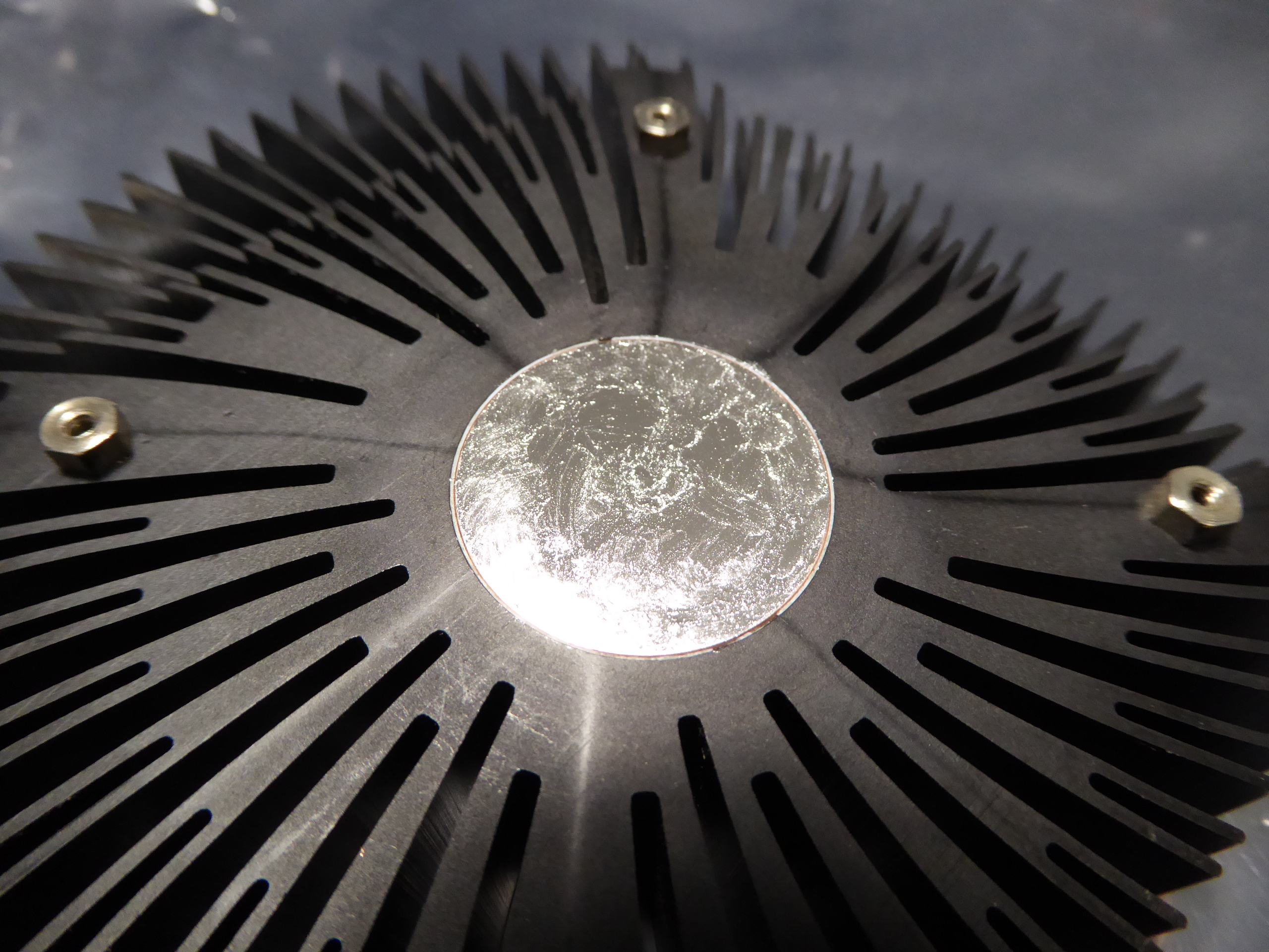
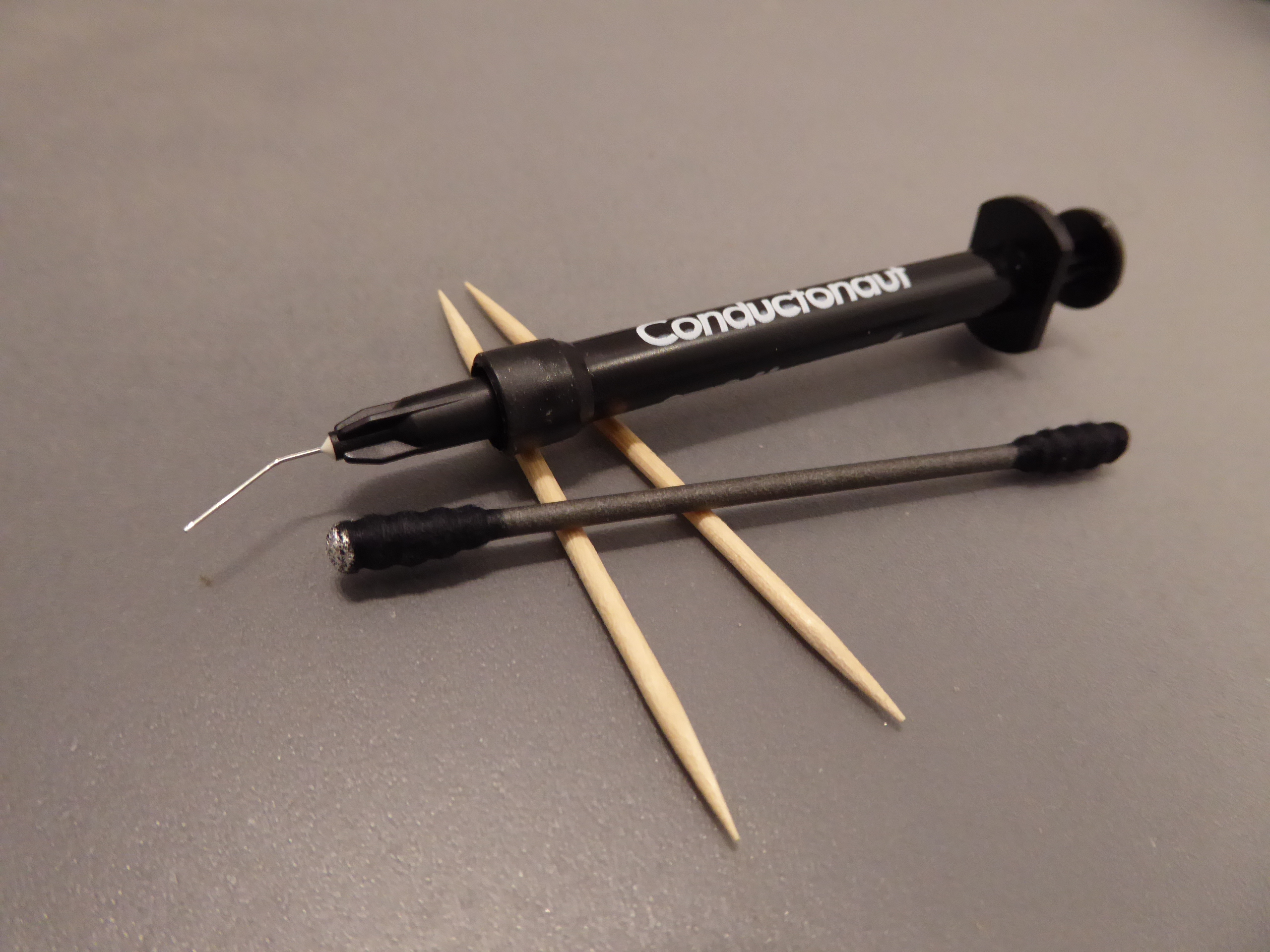
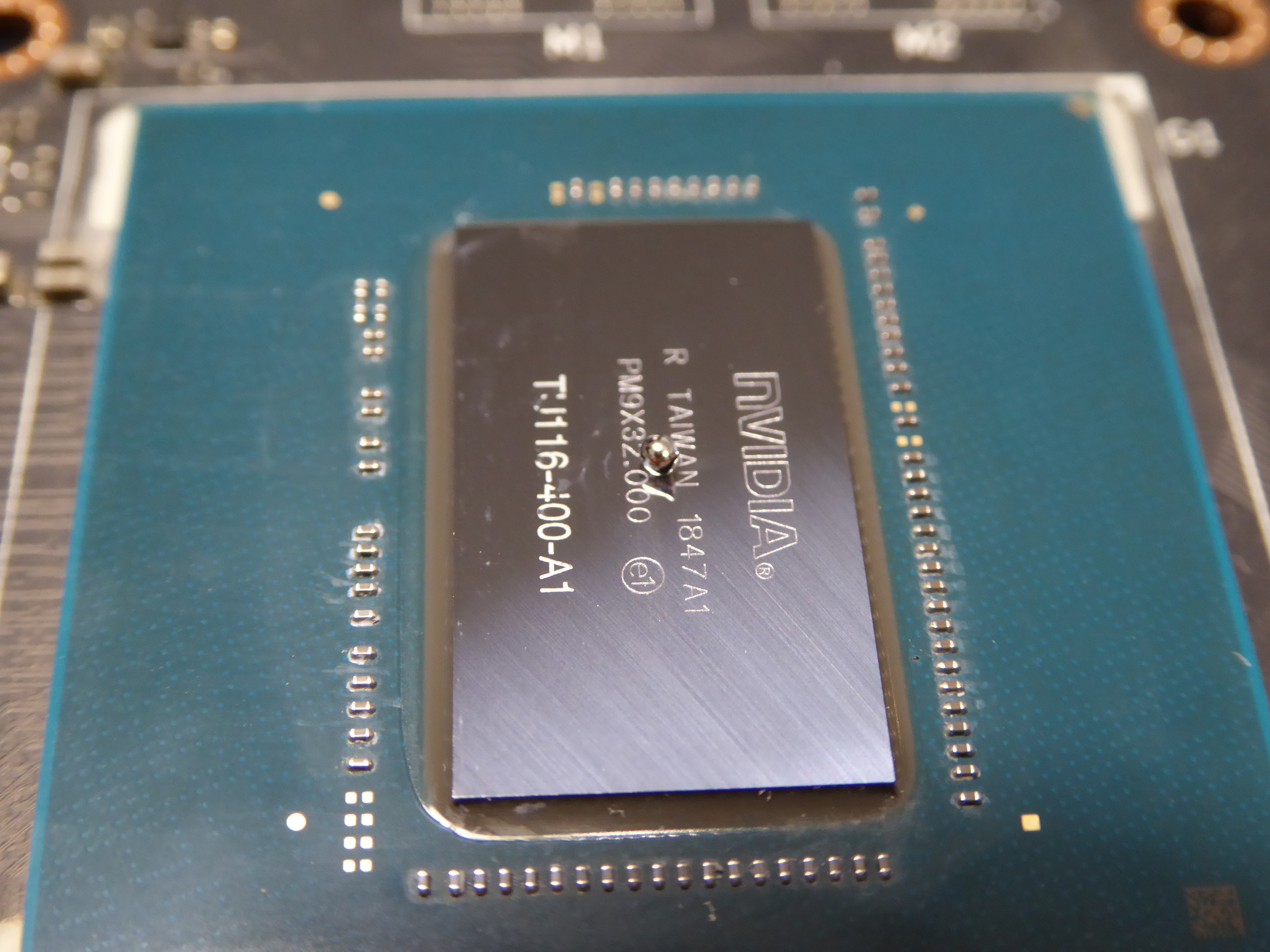
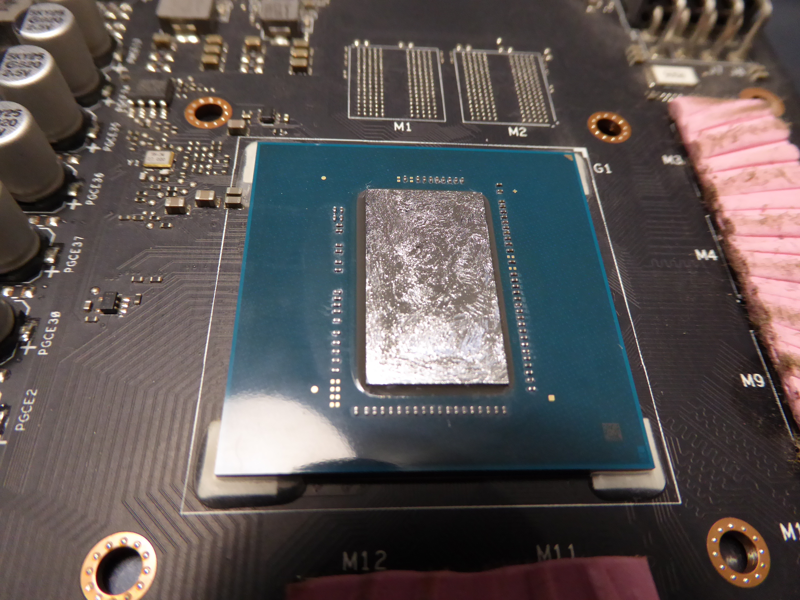
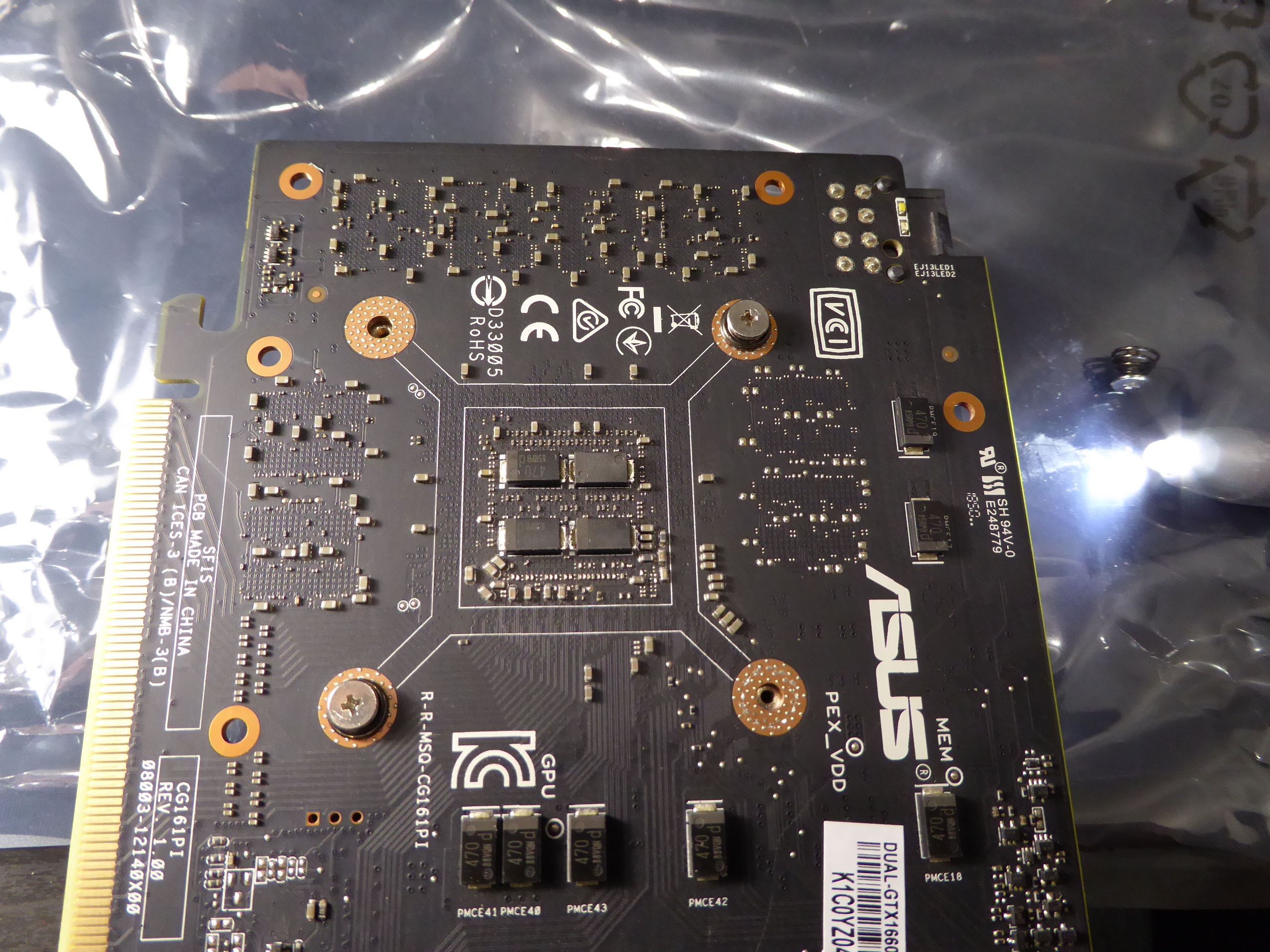
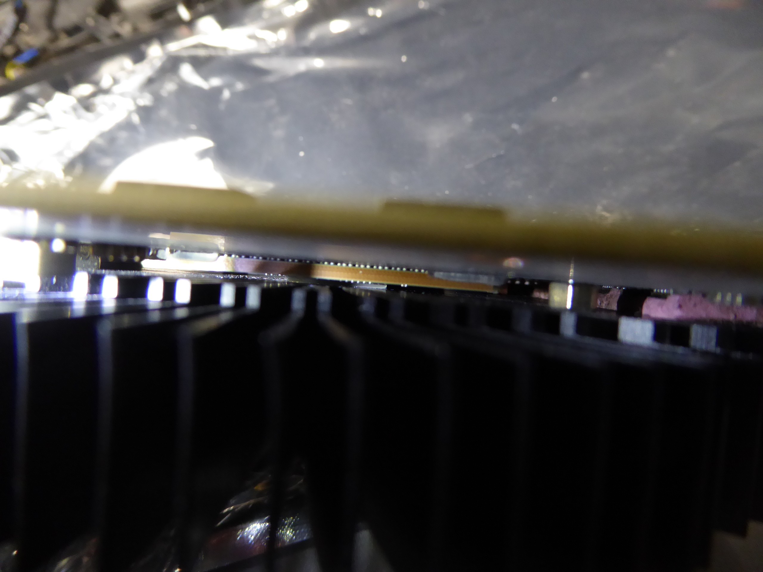
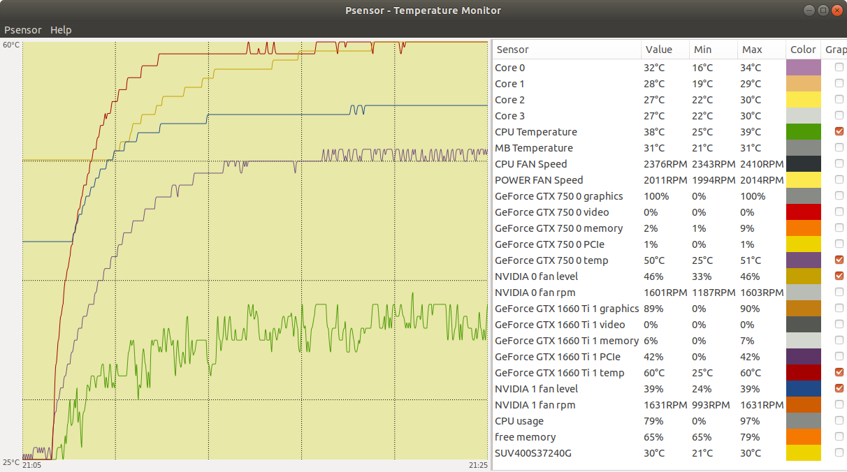
Well, I've received my Conductonaut thermal compound kit this week, and I've already tested. First of all, my special thanks to Retvari Zoltan, for bringing here this interesting topic. I'm sharing my very first experiences with it, as I promised. For this, I've selected this system. Currently it has two graphics cards installed, one GTX 1660 Ti, running preferably GPUGrid among several other GPU projects, and one GTX 750 excluded from GPUGrid, for delivering video and running all other projects. This is a BOINC Manager screenshot at the moment of starting preliminary tests. In that situation, this is a Psensor screenshot for system state. GTX 750 temperature was 53ºC while running a MilkyWay task, and GTX 1650 Ti temperature was 73ºC while running a GPUGrid task. Then, I suspended activity in BOINC Manager, and GTX 1650 Ti temperature dropped 47ºC, from 73ºC to 26ºC, in about 8 minutes. Too big and fast temperature fall for me to feel comfortable. I restarted activity again, and a subsequent temperature raise can be seen from 26ºC to 71ºC. Such sudden temperature changes suppose a mechanical overstress to GPU due to cantractions and dilations. This might reduce its life expectancy! So I chose GTX 1650 Ti to test Conductonaut. This is the same card that was object for this other thread. I started by dismounting cooler's fans and cleaning them. Then, I dismounted GPU cooler by unscrewing its 4 spring-loaded mounting screws, and I cleaned it also. Next step was cleaning thorougly GPU chip, as can be seen in "before" and "after" images. I managed to carefully remove all thermal paste remains between capacitors by means of wooden toothpicks, and finally cleaned all chip surfaces with isopropanol-dampened cotton swabs. Now, it's time for Conductonaut release... Starting with a small drop at the center of cooler's copper core, then gradually spreading it until covering all copper surface. I payed special attention for not to reach aluminium zones, as Conductonaut is expresely contraindicated for them. For spreading, synthetic-tissue headed swabs are supplied in Conductonaut kit. And they work for this purpose better than I expected. Time now for silicon surface of GPU chip, following the same procedure. Once surfaces were treated with thermal compound, graphics card was rebuilt in reverse order than dismounted. Starting with GPU cooler, paying special attention for tight coincidence between Printed Circuit Board holes and cooler's ones. The best way for me: laying cooler on the table with threaded mounting holes facing up, and then slowly lowering PCB while looking through its holes to a final perfect match. Then, I remounted the 4 original spring-loaded screws by gradually tightening them, following a cross-pattern iterative sequence. It is hard to photograph with a domestic camera, but if the proper amount of thermal fluid is used, GPU capacitors are safe apart from contacting it. GTX 1650 Ti remounted in place, and... did it worth the job? Comparing the new temperatures with the original ones while running a GPUGrid task, a reduction from 71ºC to 60ºC can be appreciated. Definitively, it did worth the job. And I've enjoyed the moments in between!-) |
|
ServicEnginIC Send message Joined: 24 Sep 10 Posts: 595 Credit: 13,083,686,510 RAC: 31,373 Level Scientific publications |
Let's make a small correction to my own previous post: Every times a "GTX 1650 Ti" graphics card is mentioned, it should be GTX 1660 Ti. "GTX 1650 Ti" is a quimeric mix between GTX 1660 Ti and GTX 1650 models. I have a couple of GTX 1650 cards also, but I have no such temperature problems due to their lower power consumtion (75 Watts) compared to GTX 1660 Ti (120 Watts) |
|
Retvari Zoltan Send message Joined: 20 Jan 09 Posts: 2380 Credit: 16,897,957,044 RAC: 0 Level Scientific publications |
I've received my CPU IHS remover kit. It's a Rockit-88 kit. It makes the IHS removal to be the fun part of the whole process. I've changed the original thermal paste to TGC so far in these CPUs: i5-8500 i5-7500 i3-7300 i7-4790k i5-750 I've also changed the thermal paste between the IHS and the cooler to TGC. The i5-8500 and the i5-7500 runs 11°C lower than before. It was very hard to clean the i7-4790k chip, the TGC didn't spread on its surface very well. I think I have to do it again. The i5-750 is a 10 year old CPU, it runs at 78-79°C with the standard Intel (copper core) cooler, while all 4 cores are fully loaded, and the PC is in a micro ATX case (side panel is on). I'll change this cooler to a Noctua D9L, as larger coolers won't fit in this case. |
|
ServicEnginIC Send message Joined: 24 Sep 10 Posts: 595 Credit: 13,083,686,510 RAC: 31,373 Level Scientific publications |
Symptom: PSU's Main switch turned from Off to On, an sparking sound is heard, and overcurrent protection at electrical panel goes down (leaving 4 computers without power, by the way). Cause: Short circuit in PSU's driver circuit component at HVDC to DC converting stage. Solution: Replace defective PSU. (I've won in some way by exchanging the old 80+ efficiency PSU by a new modular 85+ one) Guilty component: It can be seen at this forensics image, marked as IC2 at center of picture. I like this kind of problems!: Clear diagnose and simple solution Relative tip: Most PSUs have at AC rectifying stage an NTC (Negative Temperature Coefficient) resistor (thermistor) for limiting switch on current (it can be seen, out of focus at left of above image, lentil-shaped green component). When this NTC is cold, its base resistance is in series with rectifying circuitry, thus limiting the otherwise high initial charging current for HV capacitor(s). As the current circulates, the NTC is heating and decreasing its resistance to a near-zero value. If PSU is switched off and then on in a rapid sequence, there is no time for this NTC to get cold, and its intended current limiting effect is decreased, thus causing a potentially nocive high current peak. For this reason, it is advisable to wait at least (let's say) 10 seconds from switching off to switching on again the PSU, for this component has enough time to cold. |
|
Retvari Zoltan Send message Joined: 20 Jan 09 Posts: 2380 Credit: 16,897,957,044 RAC: 0 Level Scientific publications |
Relative tip: Most PSUs have at AC rectifying stage an NTC (Negative Temperature Coefficient) resistor (thermistor) for limiting switch on current ...If the PSU is switched off and then on in a rapid sequence, the capacitors in the primary circuit don't have time to discharge, so the inrush current will be low (=no need for the NTC to cool down). Unless those capacitors are broken (= lost the most of their capacity - the visual sign of it is a bump on their top and/or a brownish grunge on the PCB around them / on their top), but in this case it's better to replace the PSU. BTW LED bulbs, other LED lighting, or other switching mode PSUs (flat TVs, set top boxes, gaming consoles, laptops, chargers, printers, etc) also could have larger inrush current (altogether), especially when you arrive at the site after an extended power outage, and all of their capacitors in their primary circuits has been discharged. It's recommended to physically switch all of them off (including PCs), or unplug those without a physical power switch before you switch on the power breaker. After the power breaker is successfully switched on (I have to do it twice in a rapid succession as there are some equipment in our home which have fixed connections to the mains), the PSUs can be switched on one by one, and then the other equipment one by one. For this reason, it is advisable to wait at least (let's say) 10 seconds from switching off to switching on again the PSU, for this component has enough time to cold.I don't think that 10 seconds is enough for the NTC to cool down. It depends on the position of the PSU: If it's at the top, a significant part of the heat from the PC will get there, therefore 10 seconds is way to short time for all the PC to cool down (10-20 minutes are more likely adequate). If the PSU is at the bottom, less time could be sufficient, especially if the fan of the PSU keeps on spinning for a minute after the PC is turned off. But if the primary capacitors are in good condition, it is unnecessary to wait to reduce the inrush current. |
|
ServicEnginIC Send message Joined: 24 Sep 10 Posts: 595 Credit: 13,083,686,510 RAC: 31,373 Level Scientific publications |
An interesting article to deepen about thermistors. There is an specific section about Inrush Current Limiting Thermistor Moreover, in most of motherboards, temperatures indicated by hardware monitor are based on thermistor sensors. |
|
Retvari Zoltan Send message Joined: 20 Jan 09 Posts: 2380 Credit: 16,897,957,044 RAC: 0 Level Scientific publications |
An interesting article to deepen about thermistors.Nice reading. I didn't know the operating temperature of these thermistors. If they operate at 80-90°C, then 10 seconds is probably enough for them to cool down to 50-60°C, so they will limit the inrush current (not that much if they start from room temperature though). |
|
ServicEnginIC Send message Joined: 24 Sep 10 Posts: 595 Credit: 13,083,686,510 RAC: 31,373 Level Scientific publications |
If they operate at 80-90°C... They do. ...then 10 seconds is probably enough for them to cool down to 50-60°C, so they will limit the inrush current (not that much if they start from room temperature though). We agree. Twenty seconds better than 10, but I wanted to state a realistic lapse for us commonly eager crunchers... |
|
ServicEnginIC Send message Joined: 24 Sep 10 Posts: 595 Credit: 13,083,686,510 RAC: 31,373 Level Scientific publications |
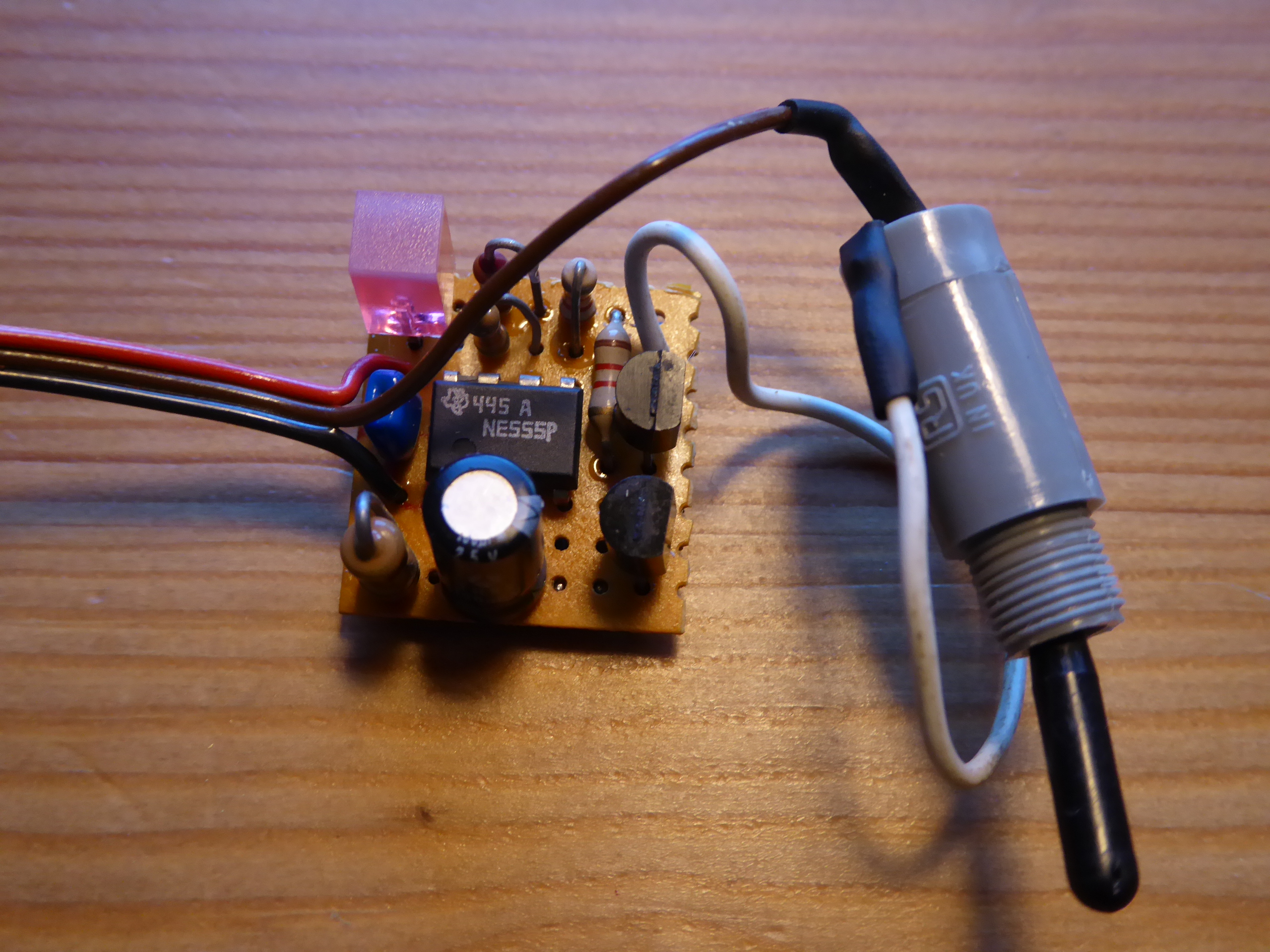
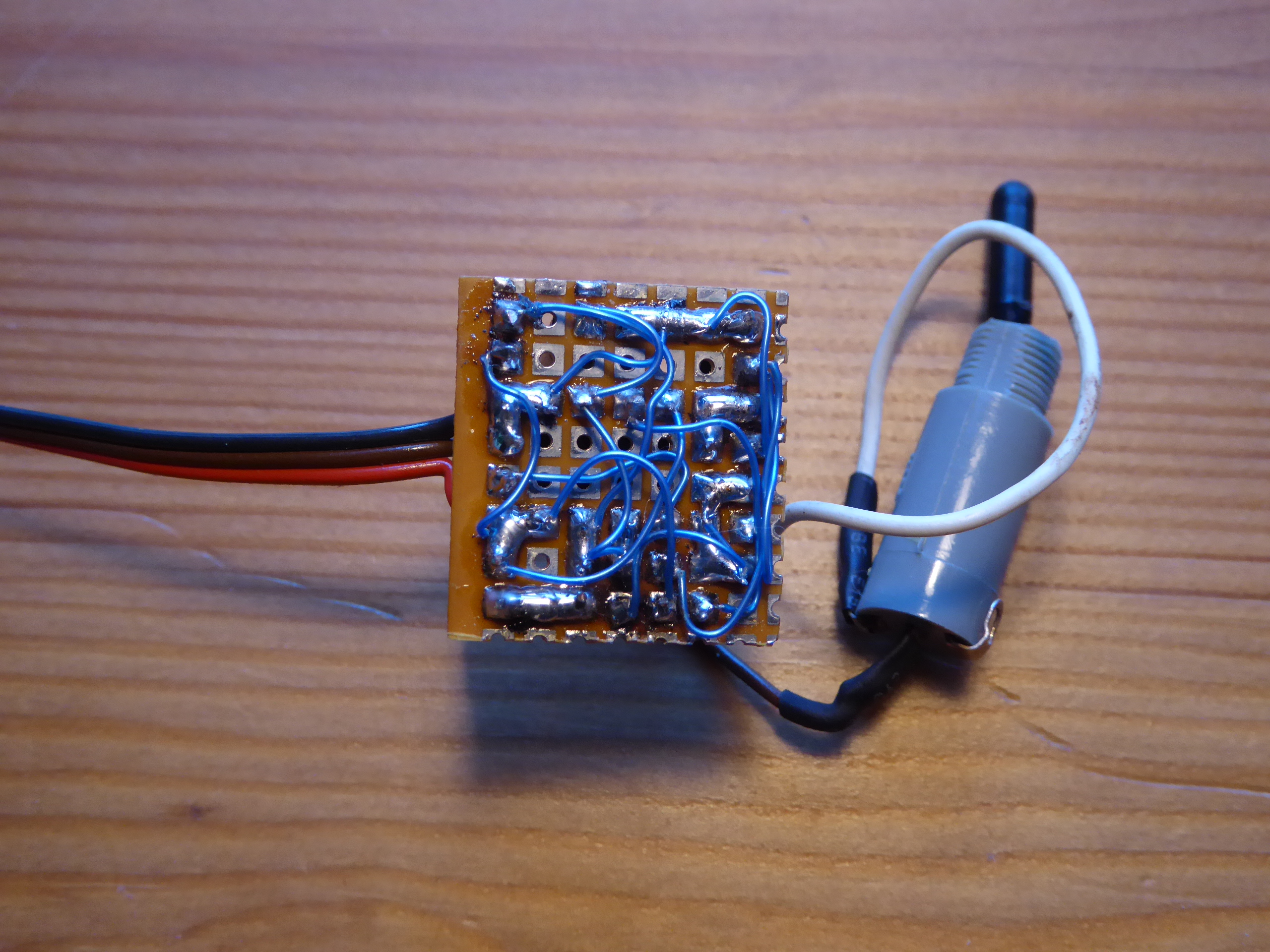
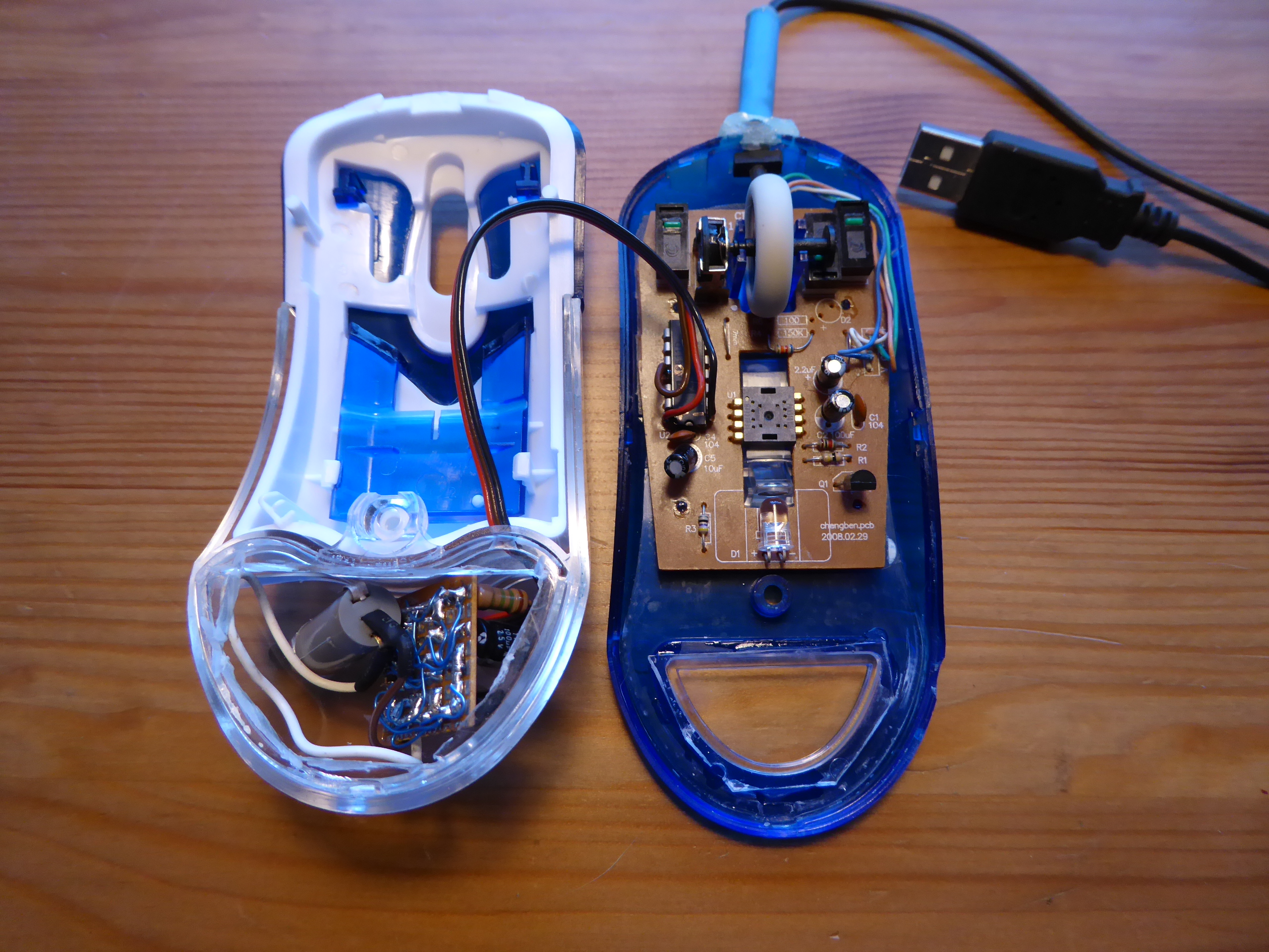
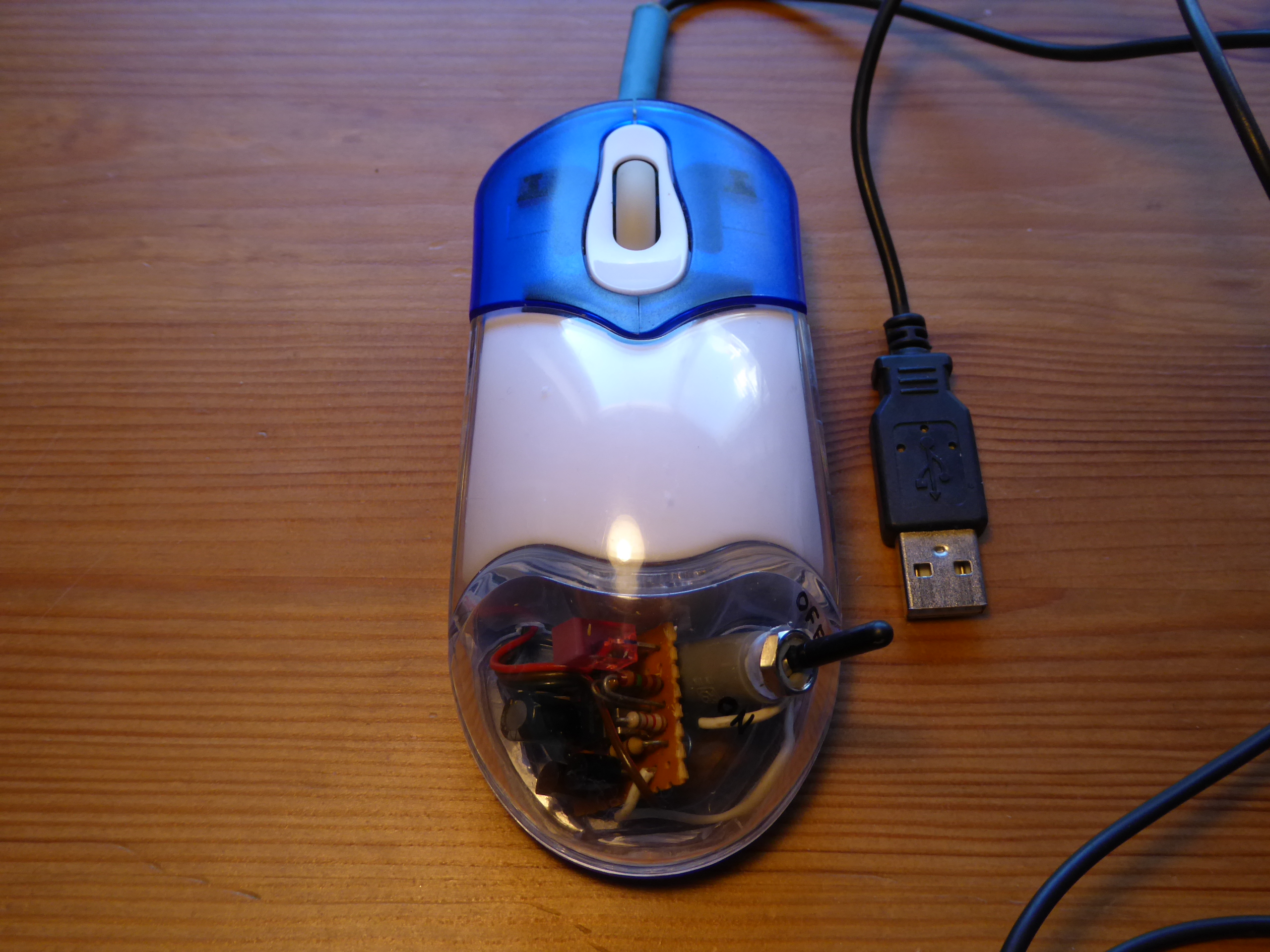
Reading this post, I thought... This can be a challenge for a hardware enthusiast! When server is plenty of WUs, everything is wonderful for our hosts with minimal intervention. But at scarcity periods, I've past many moments clicking "Update" at BOINC Manager for requesting job... So I asked myself: Is there a way to better employ this time in other tasks? I rescued some basic engineering concepts, and I spent a funny weekend while developing it. Now, after testing it to work, I'm pleased to share with those of you interested to try. I had an old souvenir mouse stored in a drawer. I dismounted it and took as starting point. Then, I designed the electrical circuit, I gathered the necessary material, and I got to work. This is the resulting circuit as seen from top. And this is as seen from bottom. It is made with a technic I used to employ when I studied, soldering point to point by means of wire-wrapping cable. Now time to integrate at mouse circuitry and assembly. And here is the final result. Does it work as intended? Yes, it does! This combination sends an automatic request for tasks about every two minutes. I've tested it on my fastest crunching-only host, for downloaded WUs (if any) to be returned on the day. Finally: As soon as I showed it to my son, he asked me: You know that there are software applications that do the same, don't you? Yes, I do, but... This is the hardware enthusiast's corner! |
|
Send message Joined: 13 Dec 17 Posts: 1424 Credit: 9,189,946,190 RAC: 0 Level Scientific publications |
Thanks for an enjoyable project tour. There is much to be said and gained from cobbling a solution together, inelegant though it might be of bits and pieces scrabbled from the bit bucket of cast off parts. At least exercise of the old grey matter was performed. |

©2026 Universitat Pompeu Fabra