The hardware enthusiast's corner
Message boards :
Number crunching :
The hardware enthusiast's corner
Message board moderation
Previous · 1 . . . 6 · 7 · 8 · 9 · 10 · 11 · 12 . . . 16 · Next
| Author | Message |
|---|---|
|
Send message Joined: 13 Dec 17 Posts: 1424 Credit: 9,189,946,190 RAC: 2 Level Scientific publications |
I'm interested in what changes the new ATX12VO standard is going to cause in the industry. A lot more motherboard real estate is going to be used up by 12V DC-DC inverters to create the +5 and +3.3V needed for SATA storage devices. Also the SATA power connectors will have to move off the power supply and onto the motherboard. Benefit will be no more burnt up 12V pins, melted Molex housings and yellow wires on the ATX 24-pin motherboard connector. The pin and wire gauge will go up considerably to handle the higher current draws on the 12V lines. Disadvantages will be even less multi-PCIE slot motherboards that only support a single gpu likely. Probably will force more people onto the HEDT and server platforms that need to host multiple gpus. |
 ServicEnginIC ServicEnginICSend message Joined: 24 Sep 10 Posts: 595 Credit: 13,083,686,510 RAC: 745,928 Level Scientific publications |
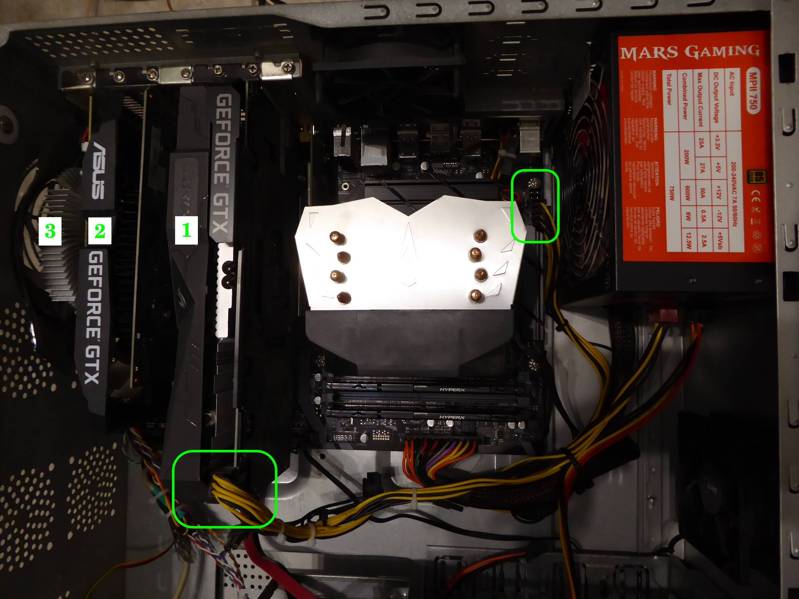
Sorry for diverting attention once again away from the recent discussion. Currently I am very confused as to what PSU characteristics are required... bozz4science,You're welcome. Every question regarding hardware is on topic here. And this has lead me to learn new subjects thanks to Ian&Steve C. and Keith Myers kind clarifications. On the practical side: it won't hurt anything to plug it in if you have it. if you don't have the extra connector, don't worry about it, you don't need to replace the PSU just for that connector. +1 I've been running this triple GPU system for months without any problem. It is Host #480458 at GPUGrid. Motherboard is a Gigabyte Z390 UD for LGA1151 processors, and it has three PCI express slots for graphics cards. Motherboard's extra four pins supply connector is left free, due to 750 Watts PSU hasn't connection available to match it. All three graphics cards are based on GTX 1650 GPU. This way, there isn't any problem when restarting GPUGrid tasks between them. Two of the cards are getting their power directly from PCIE slots (cards 2 and 3). Their rated TDP is 75 Watts each one. And I chose a model for card number 1 with an extra PCIE 6 pin power connector, for not stressing motherboard supply too much. This last card is a factory overclocked model, with a rated TDP increased to 85 Watts. |
|
Send message Joined: 8 Aug 19 Posts: 252 Credit: 458,054,251 RAC: 0 Level Scientific publications |
I've been running this triple GPU system for months without any problem. It is Host #480458 at GPUGrid. I thought I solved the issue of the extra 4-pin CPU power input by using a 4 to 2x4 pin splitter adaptor. I guess it probably was a waste of time and money powering a 65W i5-10400 but MSI stated that all the CPU power plugs must be connected when I couldn't get it to boot. Turns out Keith Myers nailed the problem as bent processor pins. This thread is awesome (grosso) for us, ServicEnginIC. Thanks again. |
|
Send message Joined: 8 Aug 19 Posts: 252 Credit: 458,054,251 RAC: 0 Level Scientific publications |
Wow, a double posting! How'd I rate that? |
|
ServicEnginIC Send message Joined: 24 Sep 10 Posts: 595 Credit: 13,083,686,510 RAC: 745,928 Level Scientific publications |
Taken from the manual of recently mentioned Z390 UD motherboard: Notice the last warning on the picture... Perhaps not all hardware handlers know this... 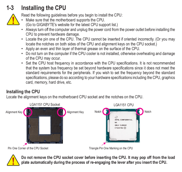 |
|
Retvari Zoltan Send message Joined: 20 Jan 09 Posts: 2380 Credit: 16,897,957,044 RAC: 0 Level Scientific publications |
I guess it probably was a waste of time and money powering a 65W i5-10400 but MSI stated that all the CPU power plugs must be connected when I couldn't get it to boot. Turns out Keith Myers nailed the problem as bent processor pinsYou have found the reason of your system's boot failure, and the way you've fixed it tells that it has nothing to do with the number of power connectors, yet you conclude that you don't need the extra 4-pin power connector. The real reason of this incorrect conclusion is that Intel made you think that your i5-10400 consumes 65W, while in real life it consumes about 50% more of that when you actually use it. You can check the actual power consumption with CoreTemp (or similar tools). Originally (in electronics) TDP stands for Total Dissipated Power, which is a real life measure of the sum of the power dissipation of all components at full load. This is used for the design of the cooling solution to make critical components stay under their maximum allowed working temperature. Intel changed the definition of TDP: Thermal Design Power, which may look the same, but listen carefully every word of their definition: What is Thermal Design Power (TDP)?Have you noticed the word "theoretical"? I assure you, that real world workloads (like crunching) are way beyond that, therefore you should not design the CPU power lines and cooling of cruncher PCs by their TDP figures. They are giving a quite polite hint of it: What is the maximum power consumption for my processor?The final blow on their definition of TDP is revealed when you click on the TDP text or the question mark next to it on any processor's product specification page (for example the i5-10400) TDPThis definition is slightly different than the previous one, but sums the previous two quoutes: The main point is that the i5-10400 has a TDP of 65W on 2.9GHz, all cores active, while they advertise it as a 4.3GHz CPU, which actually is, but its TDP is much higher than 65W on 4.3GHz. This is true for all Intel processors which have a "base frequency" and a "turbo frequency". Intel never disclose the TDP of their processors at "turbo frequency", but they advertise them as being that ("turbo frequency") fast. This is a questionable way of making their processors more appealing. |
|
Send message Joined: 8 Aug 19 Posts: 252 Credit: 458,054,251 RAC: 0 Level Scientific publications |
Thanks much Zoltan, yes, when I look at the MSI Afterburner hardware monitor it shows that when running around 90% capacity, my 10-400 consumes close to 70 watts so I sure won't call the extra power plug on this z-490 board unnecessary. I hope that splitting one of the power leads into two plugs doesn't cause me problems down the road. I should have upgraded to a semi-modular PSU. The current one is a EVGA 750W White model. I'm assuming that the PCIE slots are powered by these plugs also. Is that correct? That adds up to 150 watts powering 2 GTX 1650s, if so. Thanks for posting all that info, Every day is a good day to learn. |
|
Send message Joined: 8 Aug 19 Posts: 252 Credit: 458,054,251 RAC: 0 Level Scientific publications |
Thank you too, ServicEnginIC. I don't recall if MSI was that detailed or not with their instruction. I admit I probably glanced at the directions and then went about slapping it in with a total lack of attention. That's what makes you guys such valuable mentors in this thread! Multi gracias! |
|
Send message Joined: 21 Feb 20 Posts: 1117 Credit: 40,876,970,595 RAC: 0 Level Scientific publications |
But the extra 4-pin IS unnecessary if you’re already using an 8-pin. The 8-pin alone can supply over 200W. Your 70W chip isn’t stressing it at all. 
|
|
Send message Joined: 13 Dec 17 Posts: 1424 Credit: 9,189,946,190 RAC: 2 Level Scientific publications |
The PCIE slots are powered mainly from the 24 pin EATX connector. Why an extra EATX12V connector on the motherboard is desirable when all the slots are occupied by high powered (200W or more gpu cards) so you don't risk burning up the 24 pin connector. Most modern cpus pull enough power to demand at least the 4 pin CPU EATX power plug connected or preferably the 8 pin connector. Most mobo manuals state the 8 pin should be connected if overclocking. Also how much power is pulled from the slot is dependent on the card hardware and firmware. The PCIE slot can support a max of 75W from the specification of which only 66W is for the 12V lines. The slot also has 3.3V lines in it that get the rest of the 75W allotment. But a card does not necessarily pull the max 66W from the slot if it is designed to pull the majority of its power from the auxiliary PCIe 12V connectors that high powered cards have. |
|
ServicEnginIC Send message Joined: 24 Sep 10 Posts: 595 Credit: 13,083,686,510 RAC: 745,928 Level Scientific publications |
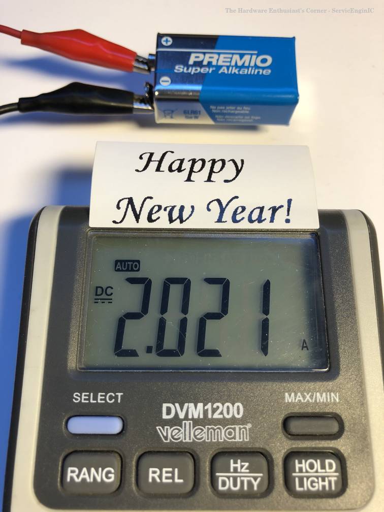
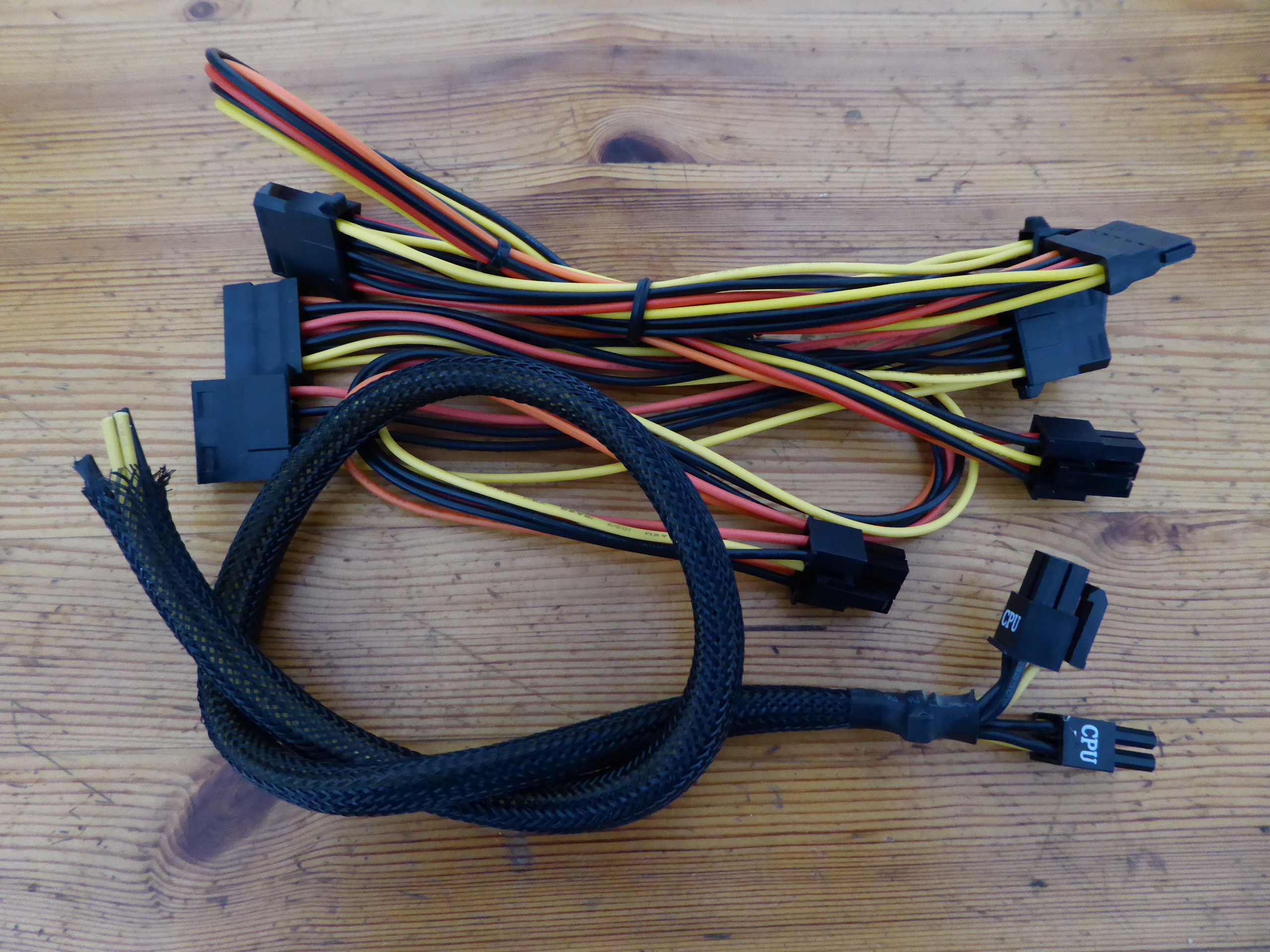
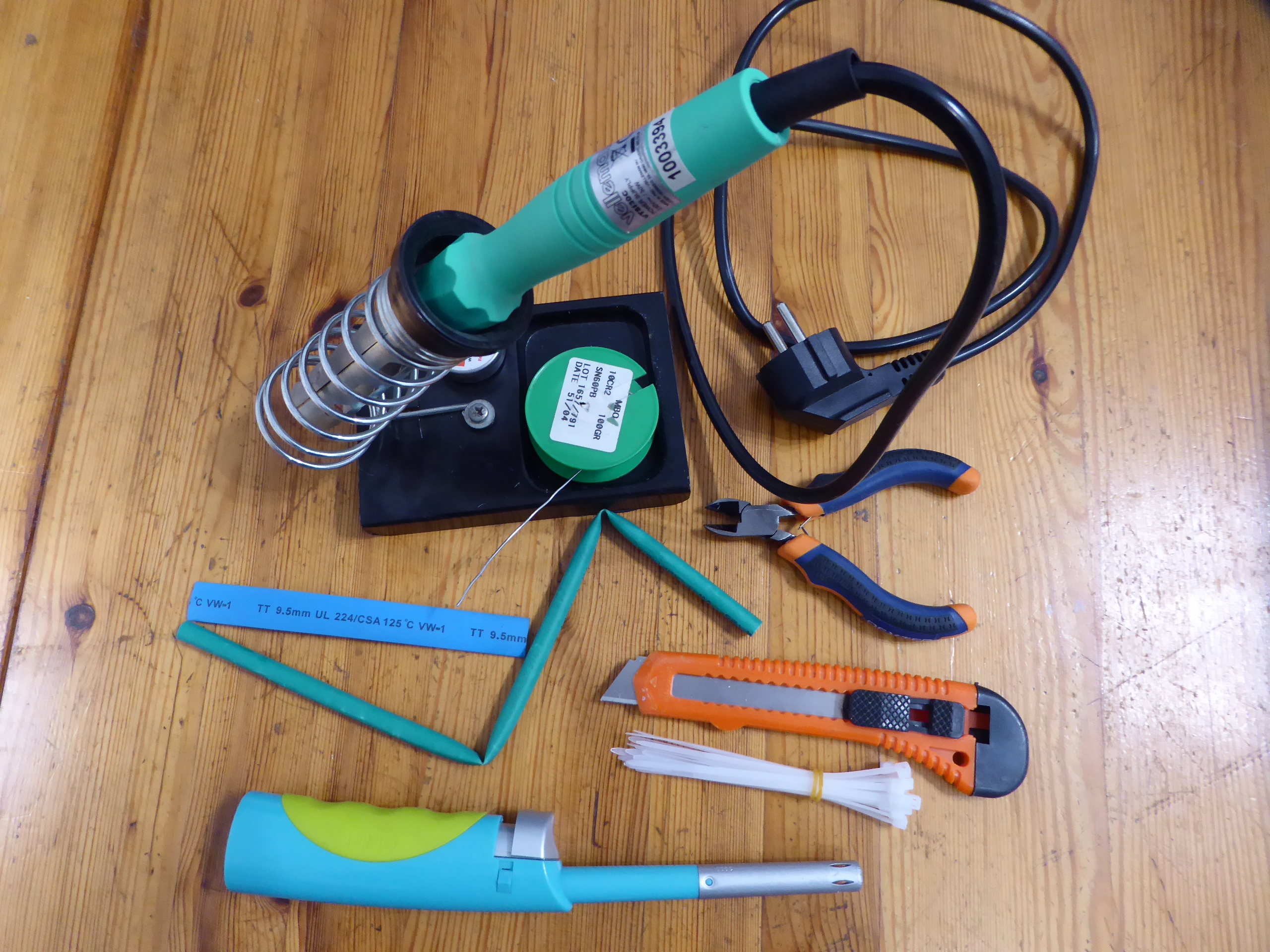
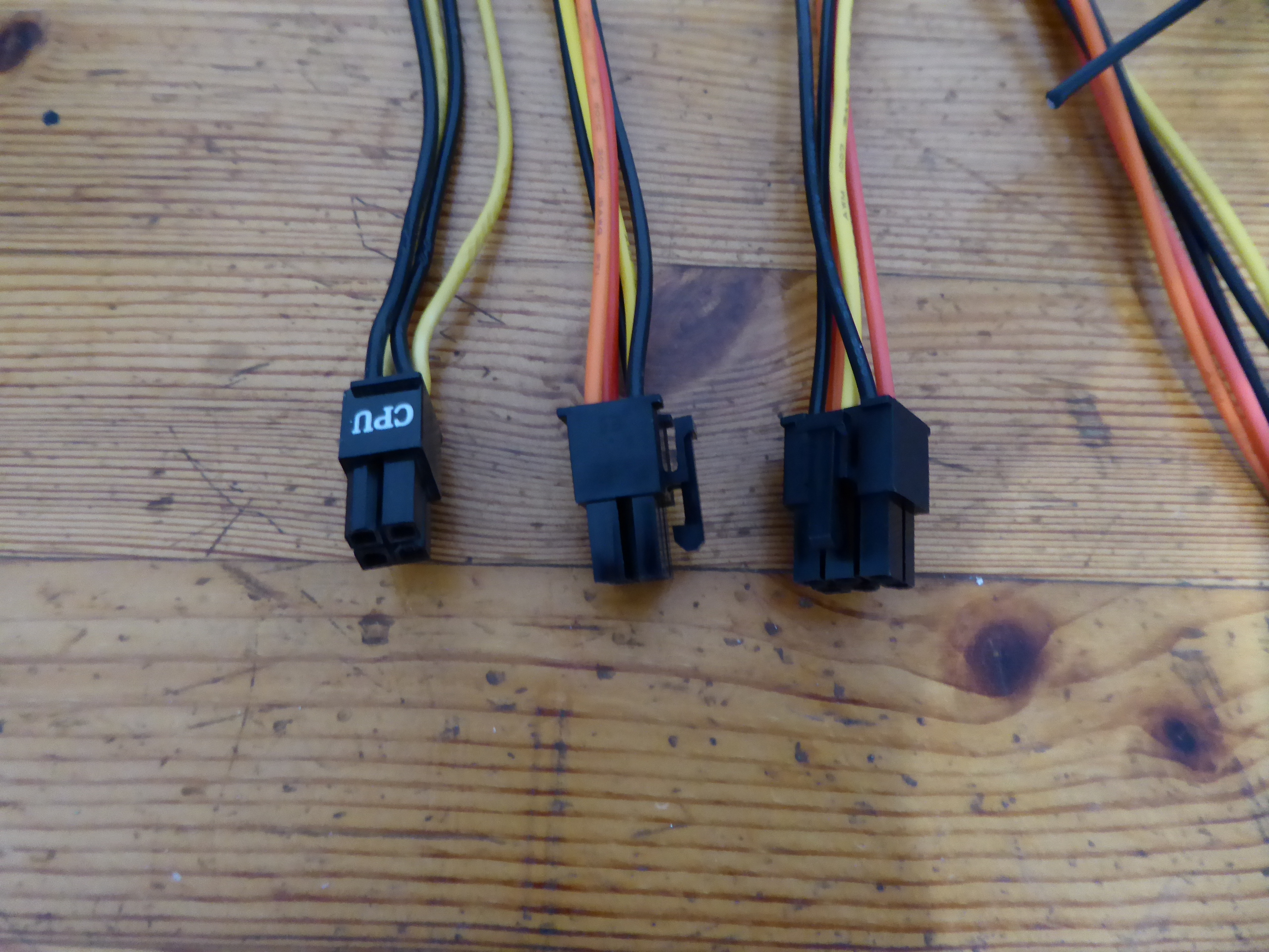
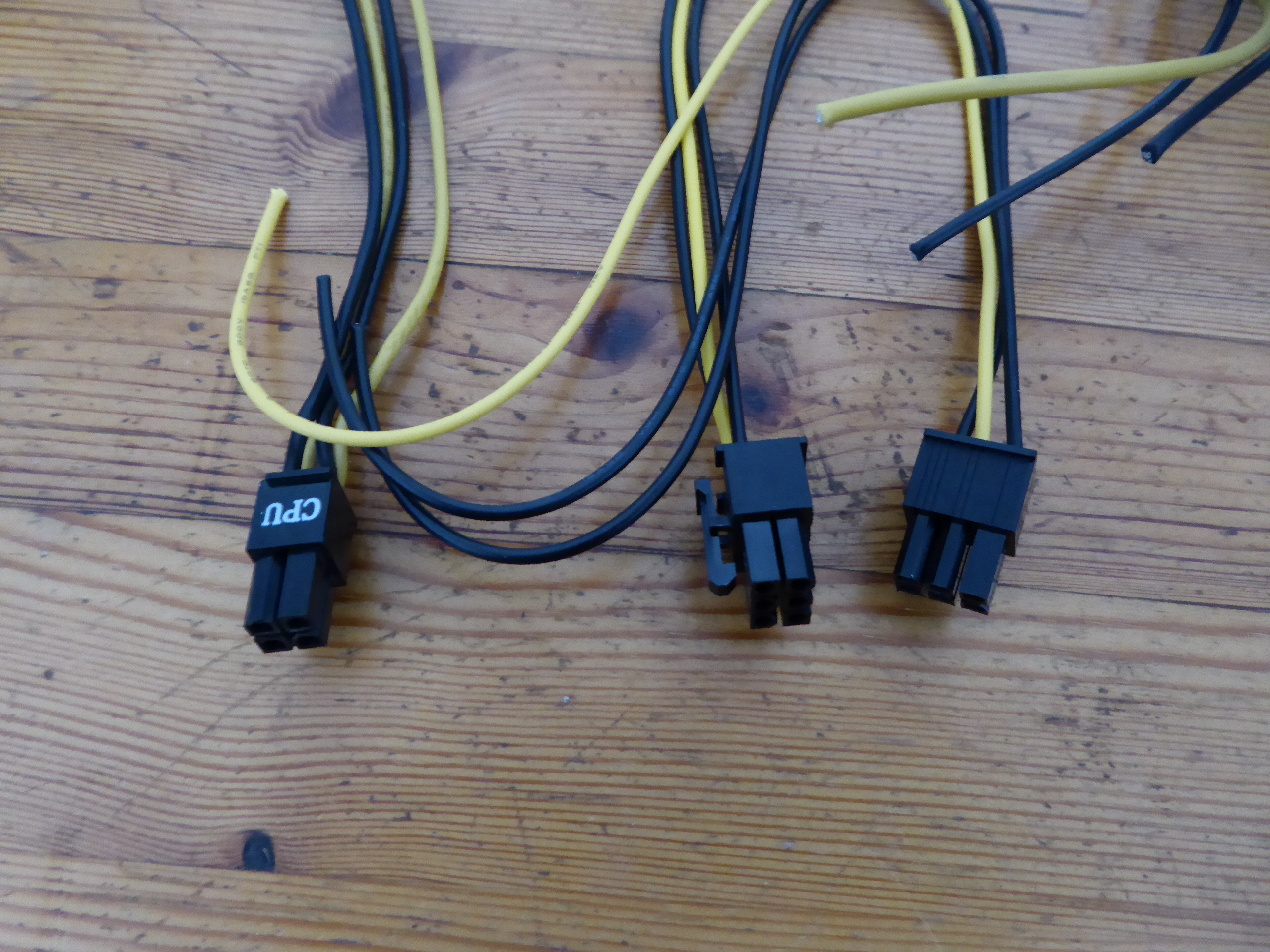
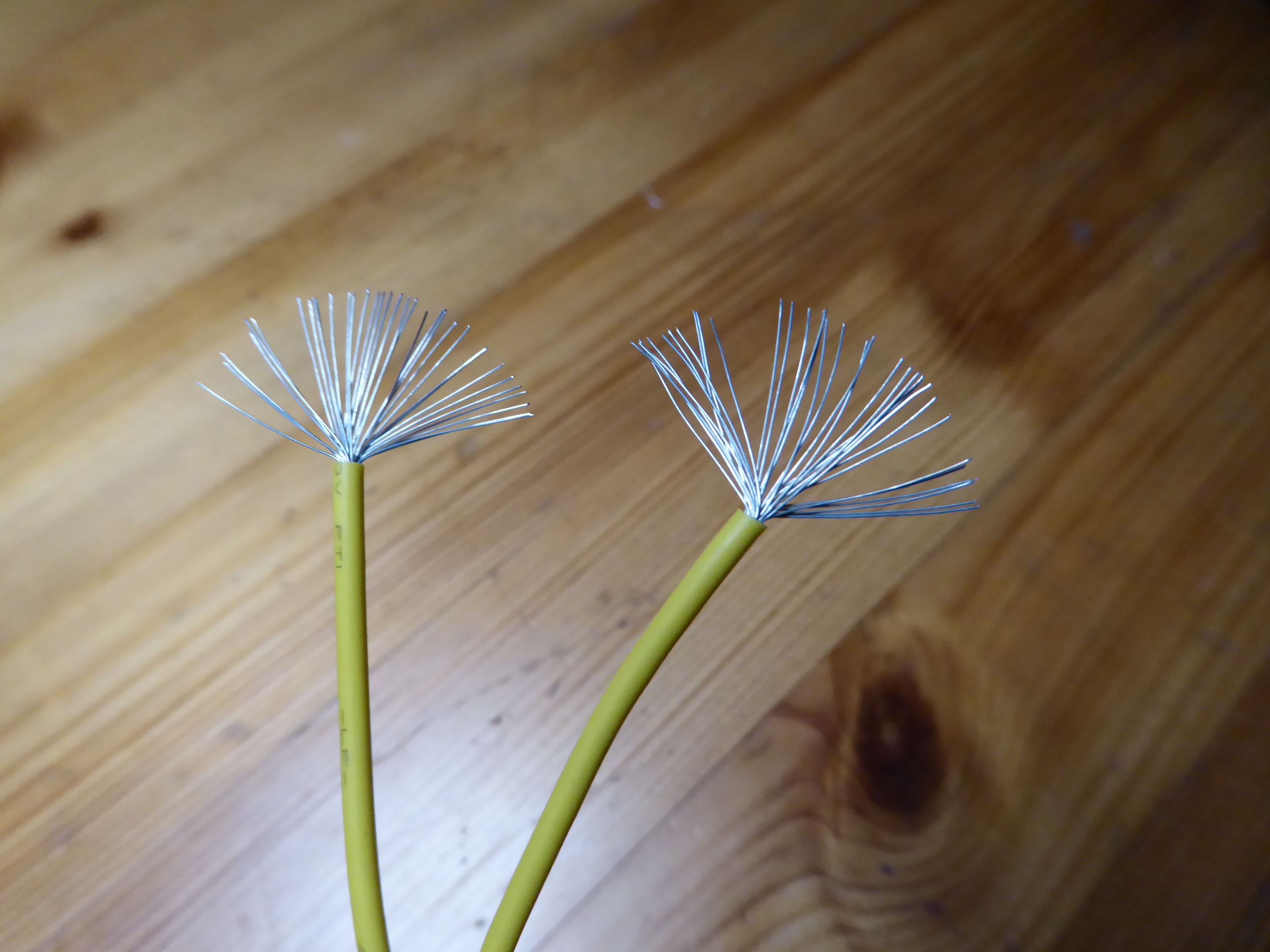
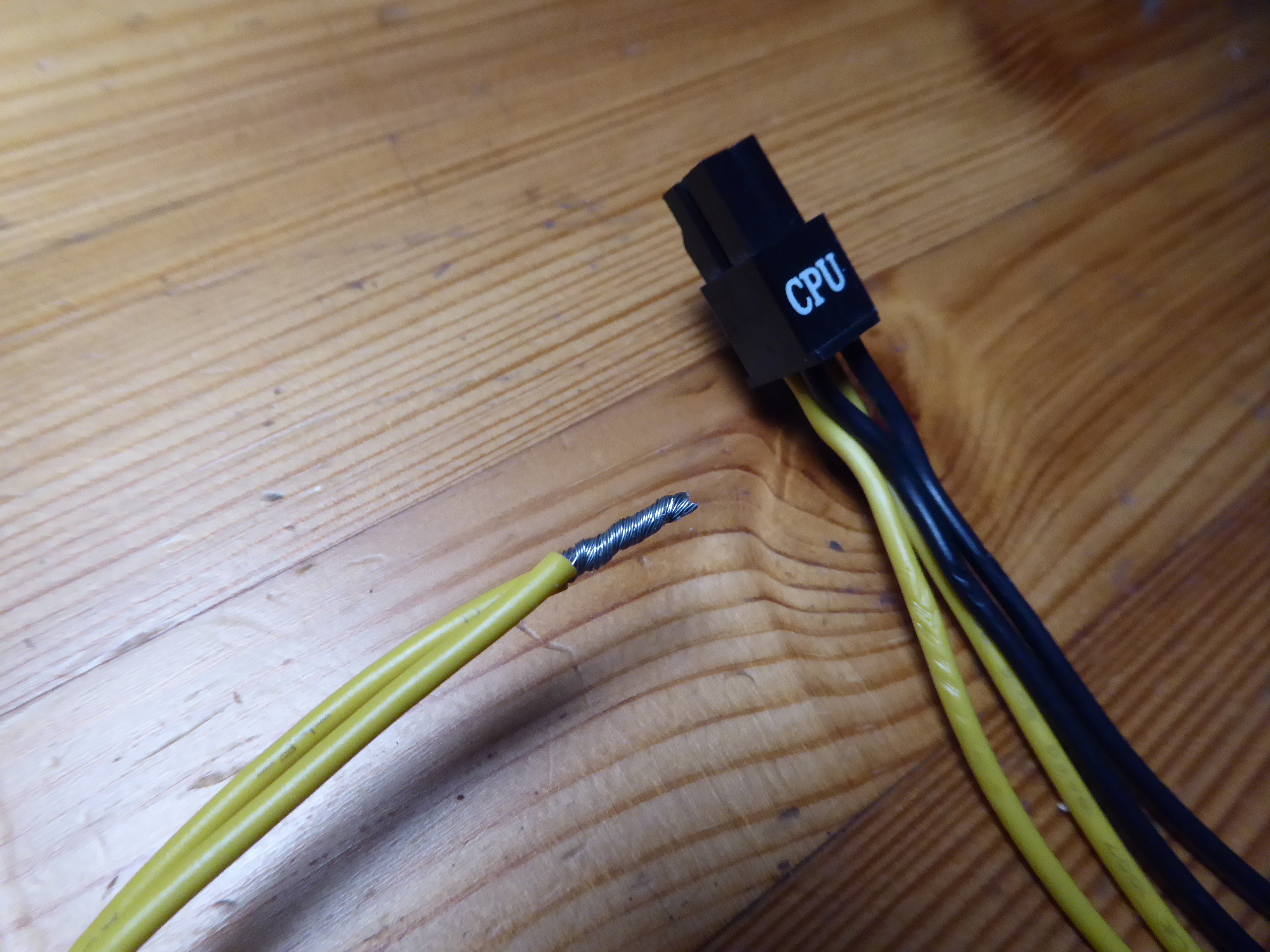
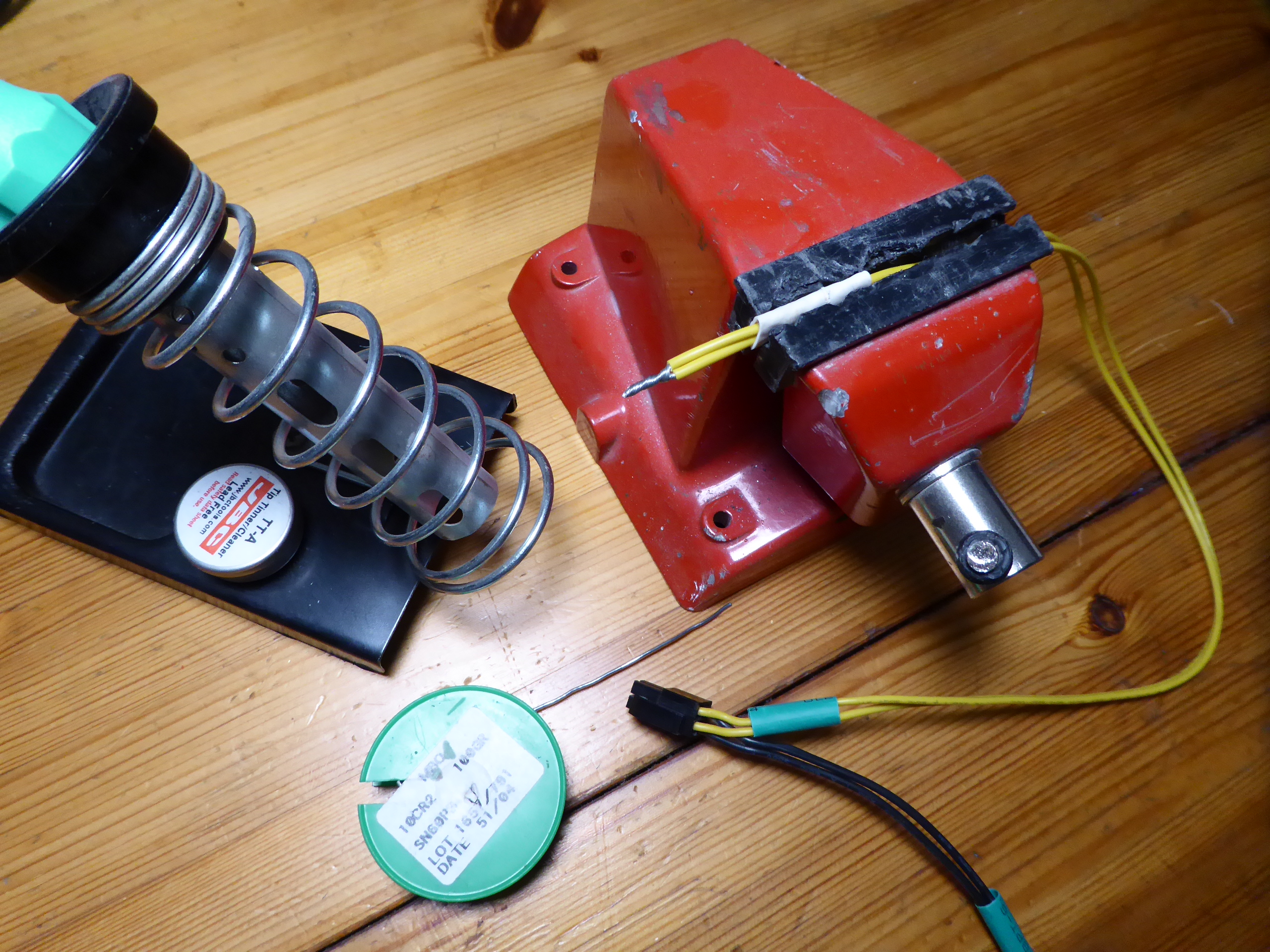
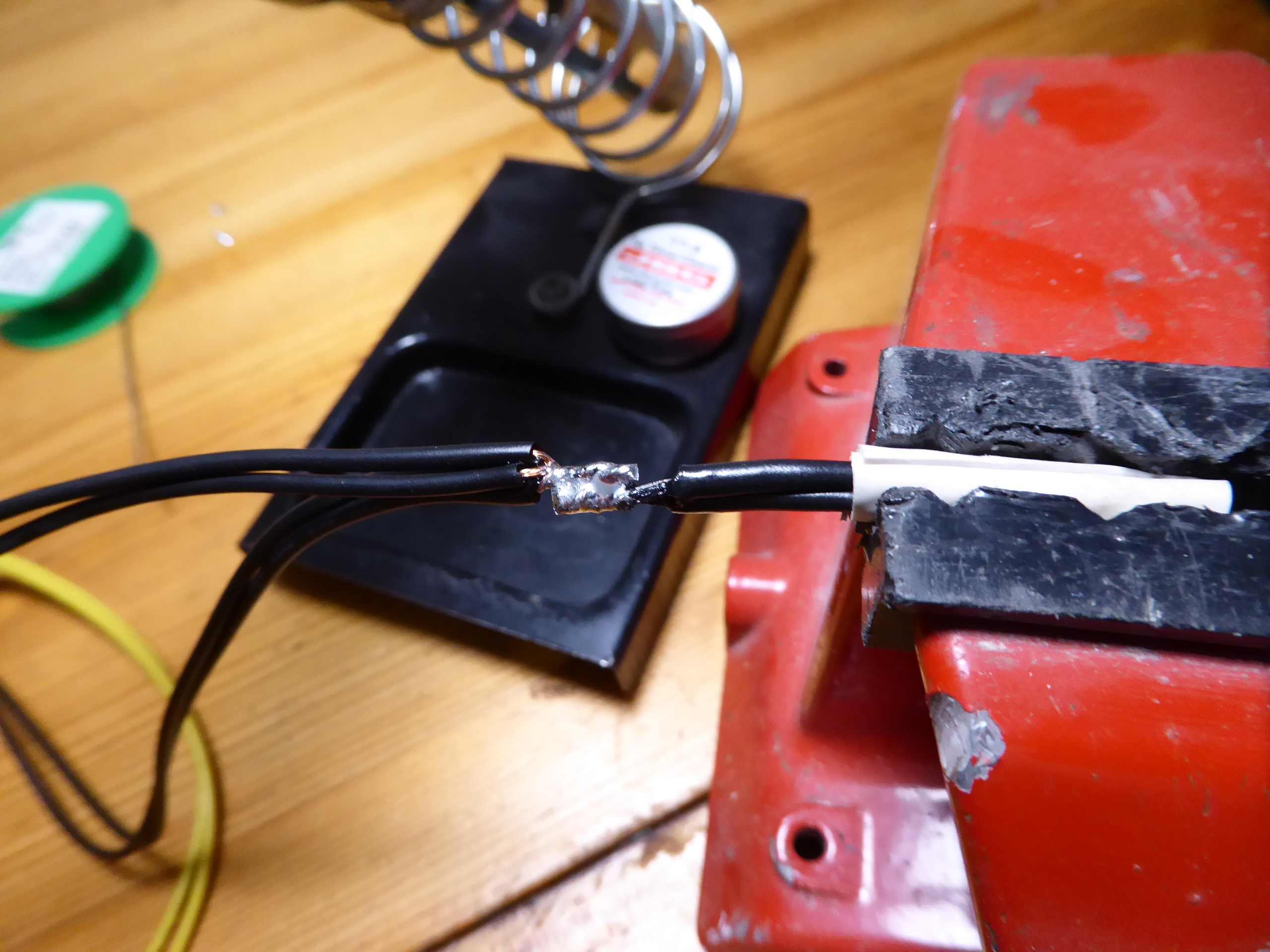
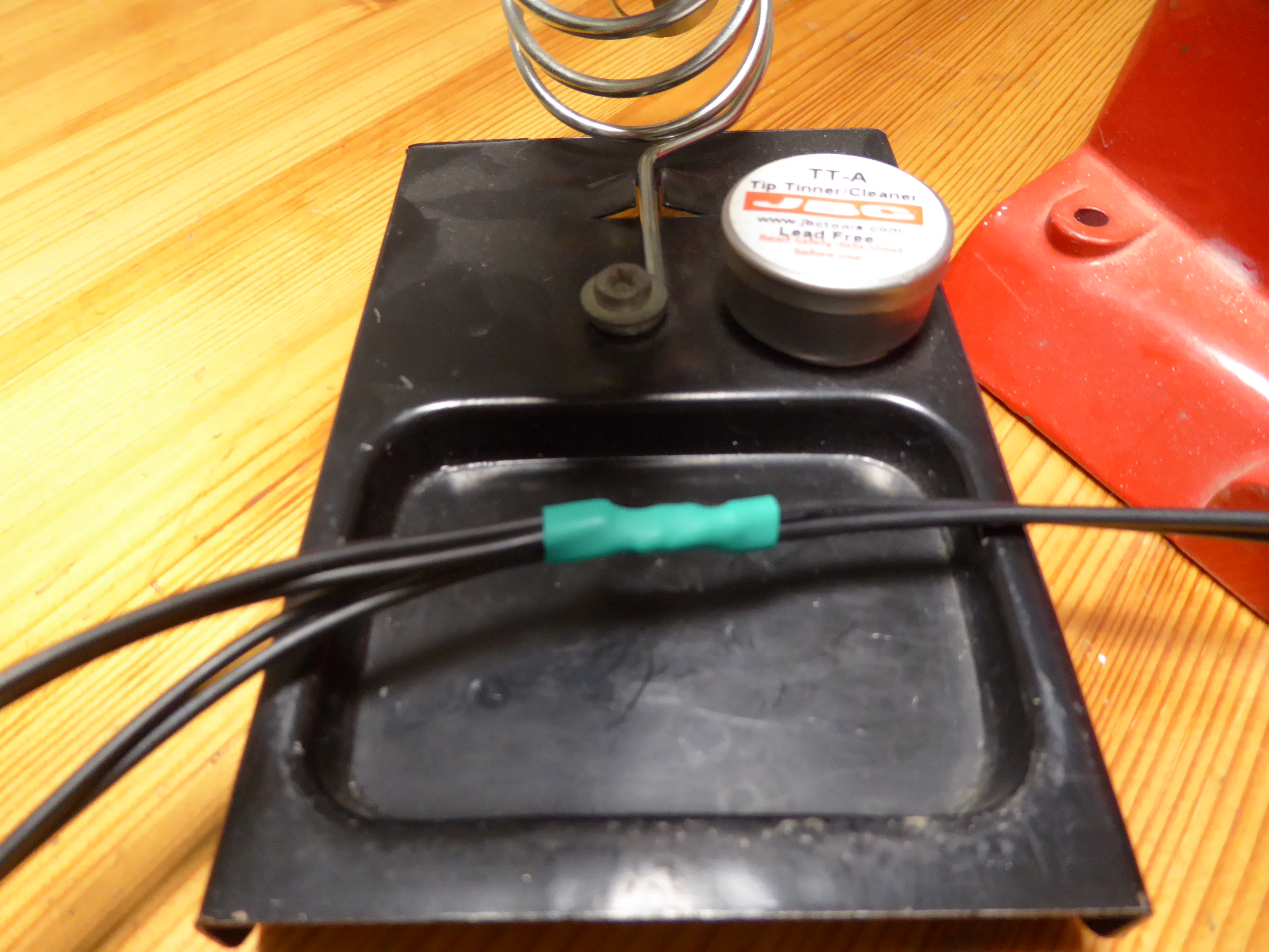
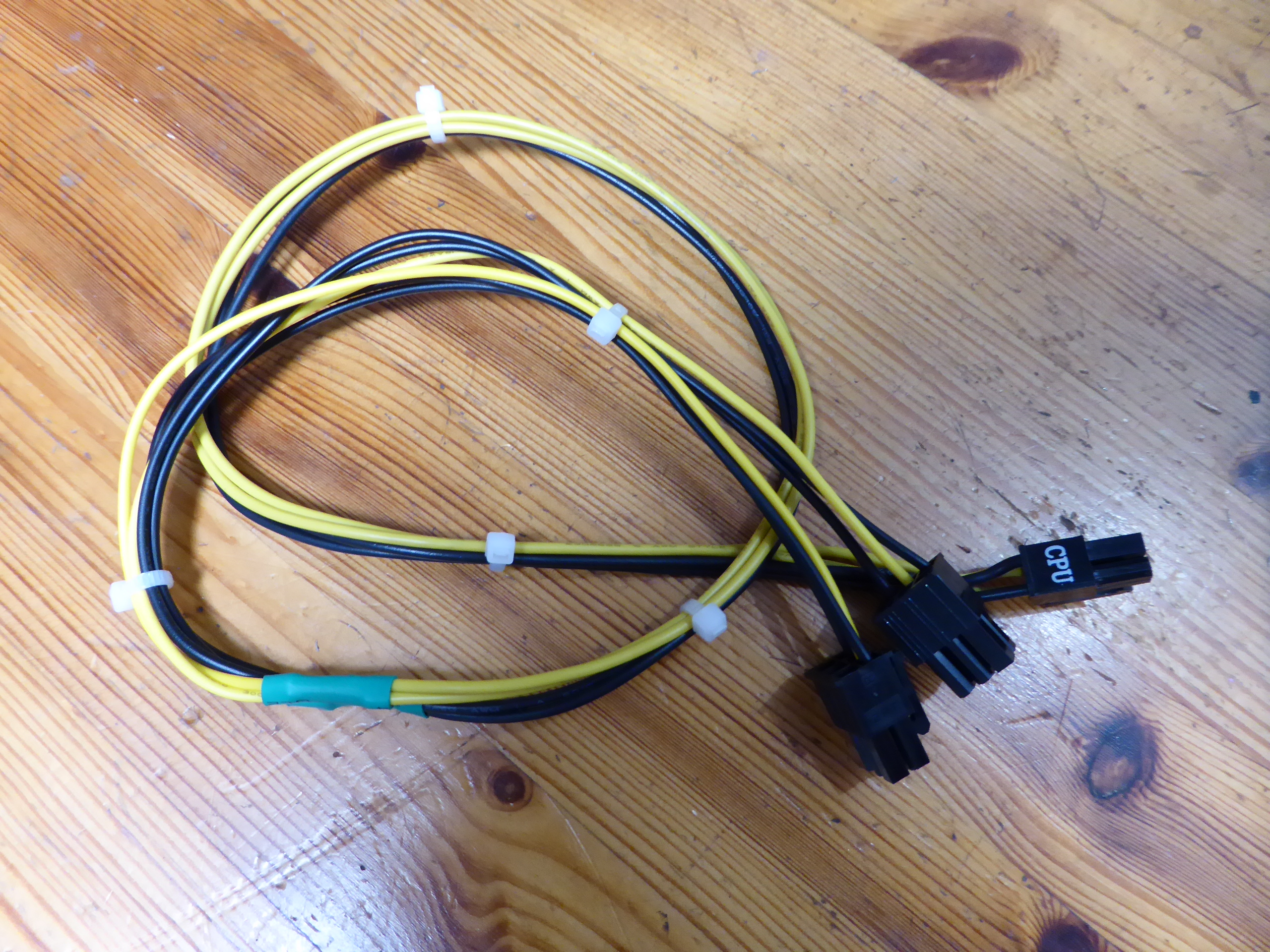
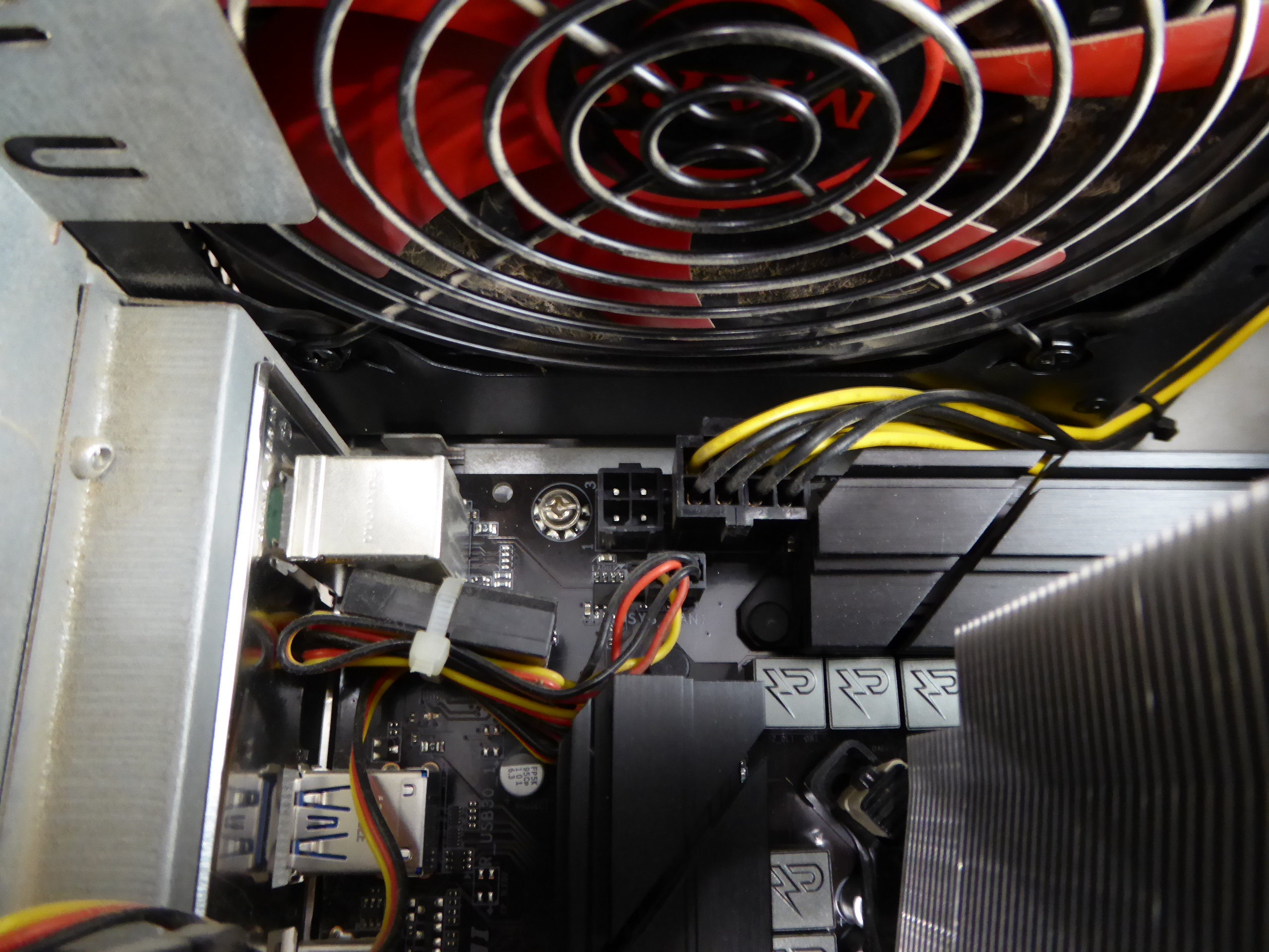
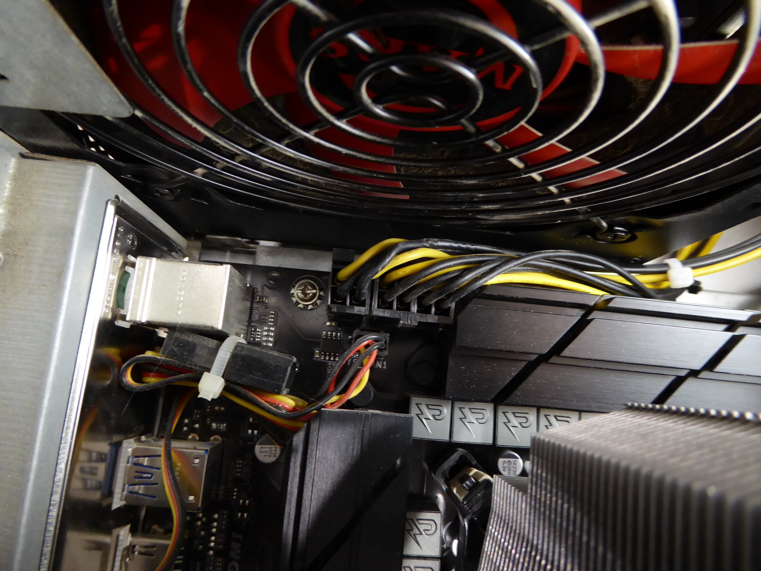
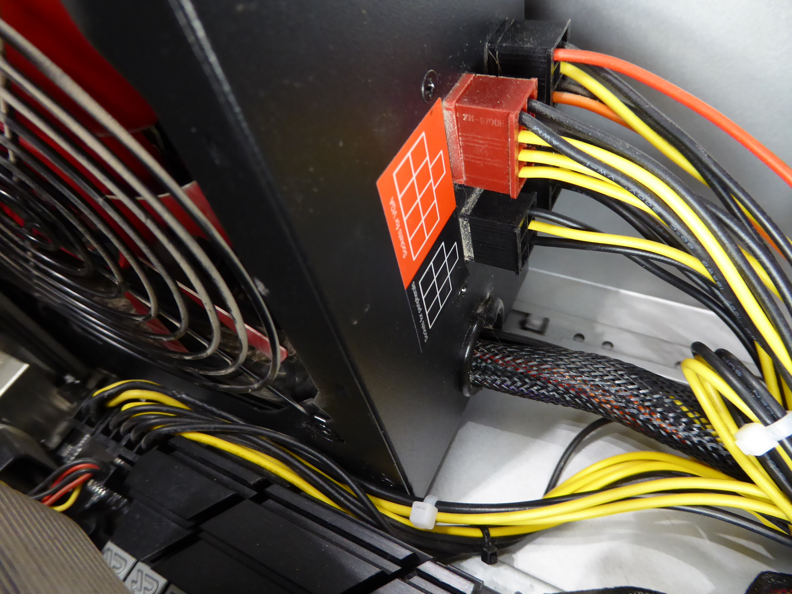
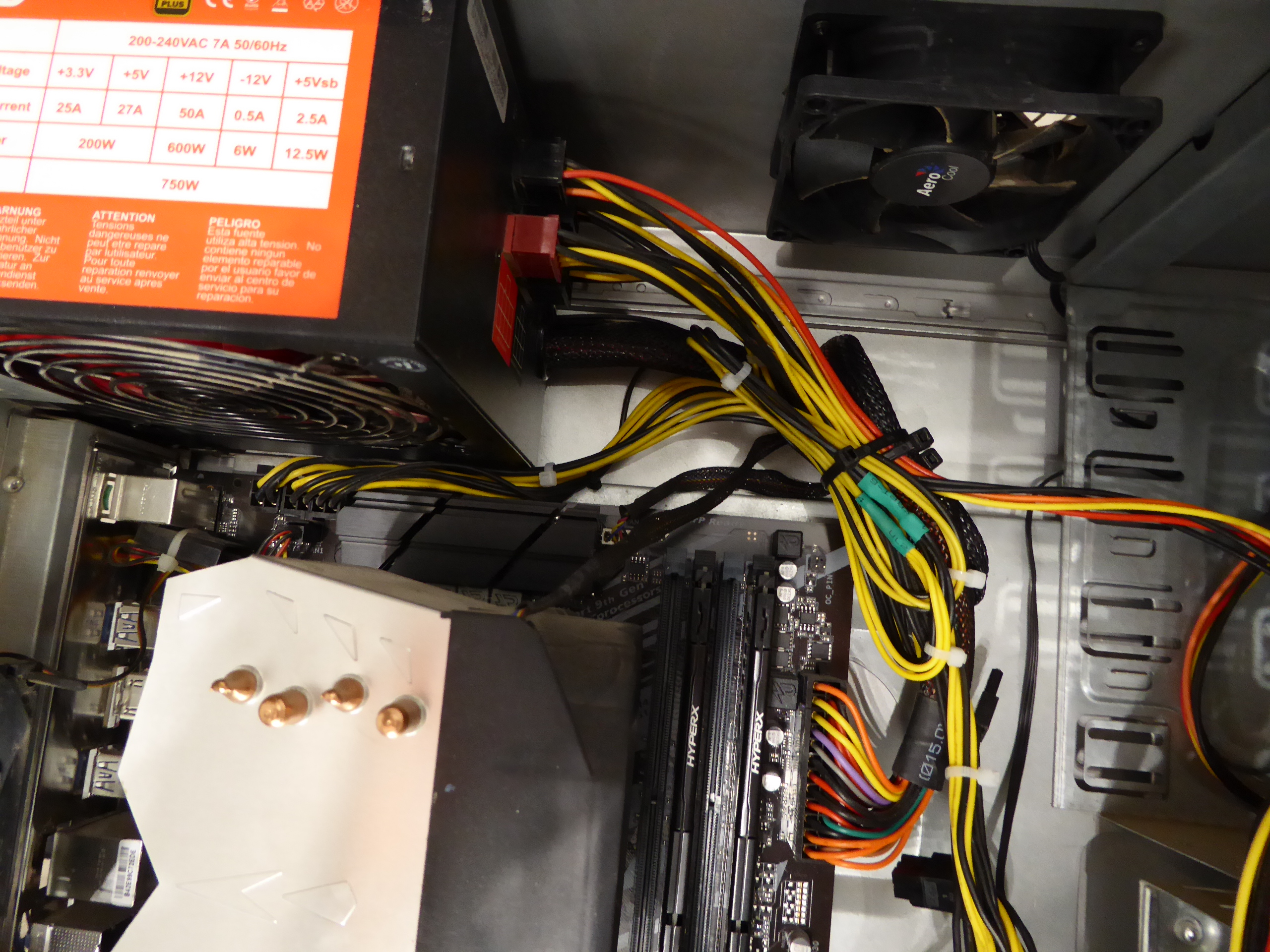
But the extra 4-pin IS unnecessary if you’re already using an 8-pin. The 8-pin alone can supply over 200W. I agree that in my case currently it is not necessary, but what if it was? I'll try to make a solution with my available resources. Returning to this triple GPU system, it is supplied by a semi-modular Mars Gaming MPII 750 PSU. This PSU has a wired 20+4 pins ATX motherboard connector, and 4+4 pins connectors for supplying motherboard with +12V. It has also one modular +12V output for supplying 2xPCIE 6+2 pins power connections, and three more combined modular outputs, two of them ramaining available. And I'd kept (just in case) cutted out CPU 4+4 pins power wirings and two combined modular cables from a broken PSU... It is all what I need, apart from some (funny) workmanship. Tools and materials required: Cutting pliers, cutter, gas lighter, soldering iron, soldering tin, thermoshrinking sleeve, and several cable ties. I'll start by separating the necessary connectors, and then retiring unnecessary red (+5V) and orange (+3,3V) wires. Now only black (ground) and yellow (+12V) wires are remaining. (- Let's plug in soldering iron now, for it to be hot enough when needed -) Then, I'm stripping about 12 mm (~1/2 inch) of insulation at every wire ending, by cutting it around carefully and peeling it. Now I'm unfolding the stripped wire ends in what I call "the shape of a peacock's tail". Then, this spreaded wire ends are overlapped and twisted together to obtain this result. (It's said that world can be divided into two groups: The one of people twisting clockwise, and the other that prefer twisting counterclockwise... It doesn't matter, the result is the same ;-) Insert now about 32 mm (~1 1/4 inch) of shrinking sleeve at each grouped wires, and push it far apart from wire ends. Let me present at this moment a tool that I initially forgot: This practical "third hand" to hold wires while soldering them. Once soldering iron is hot enough (important), heat well the stripped wire end while applying generously some soldering tin along it, as can be seen (?) at this first take video. And at this other video we can see how yellow color wires are attached together by melting their preapplied soldering tin. Finally, we're protecting bare junction with preinserted (?!?) shrinking sleeve. I usually employ the colder blue portion of a gas flame, spreading heat quikly along all the sleeve until it completely shrinks. On the same way, I'll join all black wires together, and protecting them with isolating sleeve. Once soldering tasks are finished, don't forget unpluging soldering iron, and picking up every leftovers. We will finish grouping wires by means of evenly arranged cable ties. That's all. Here we have the final result. Does it work? Here is a before and after 01, after 02, and after 03 images of Host #480458 |
|
Send message Joined: 8 Aug 19 Posts: 252 Credit: 458,054,251 RAC: 0 Level Scientific publications |
During the server outage yesterday I tried out Keith Myers' suggestion of checking the CPU socket pins to explain my missing memory channel and he was spot-on. Two bent pins, 2nd & 3rd from the bottom of the 3rd column from the right when viewing the socket with the alignment corner bottom left side. I used my smallest flat jewelers screwdriver, but it still felt a bit like using a Track Hoe to straighten a parking bollard, looking through the loops. Fortunately, my old hand was steady enough and I now have dual-channel DDR4-3000 running @ 2933 MHz, even with a locked 10-400 processor (I didn't know that was possible). My bad to diss my MSI Z490 board, it rocks! Anyway, thanks to Keith and ServicEnginIC, also anyone else who advised me on this problem. |
|
ServicEnginIC Send message Joined: 24 Sep 10 Posts: 595 Credit: 13,083,686,510 RAC: 745,928 Level Scientific publications |
Congratulations! Hurrah to your courage, and to Keith Myers for his wise advice. 🙌 |
|
Send message Joined: 13 Dec 17 Posts: 1424 Credit: 9,189,946,190 RAC: 2 Level Scientific publications |
Happy to hear of your successful socket surgery Pop. It is a bit nerve wracking to intentionally introduce any object into the field of LGA pins in a socket. But with careful patience and steady hands, you can perform some mild manipulations to get all your memory channels readable. |
|
Send message Joined: 8 Aug 19 Posts: 252 Credit: 458,054,251 RAC: 0 Level Scientific publications |
(It's said that world can be divided into two groups: The one of people twisting clockwise, and the other that prefer twisting counterclockwise... Do you suppose that has anything to do with what hemisphere you live in, amigo? I guess that question needs to be answered by rod4x4. |
|
Send message Joined: 4 Aug 14 Posts: 266 Credit: 2,219,935,054 RAC: 0 Level Scientific publications |
(It's said that world can be divided into two groups: The one of people twisting clockwise, and the other that prefer twisting counterclockwise... Clockwise or counter-clockwise, I am dizzy at the skill and precision of all of ServicEnginIC work he presents. Attention to detail is amazing! Well done ServicEnginIC! |
|
Send message Joined: 8 Aug 19 Posts: 252 Credit: 458,054,251 RAC: 0 Level Scientific publications |
(It's said that world can be divided into two groups: The one of people twisting clockwise, and the other that prefer twisting counterclockwise... Dittos, mate! I would feel quite secure knowing he serviced the ventilator I was on, were I in that situation. 👍👍 |
|
ServicEnginIC Send message Joined: 24 Sep 10 Posts: 595 Credit: 13,083,686,510 RAC: 745,928 Level Scientific publications |
 |
|
Send message Joined: 8 Aug 19 Posts: 252 Credit: 458,054,251 RAC: 0 Level Scientific publications |
I've a discovery to share with anyone who runs a Dell OptiPlex mini-tower. Because of the design of the CPU cooler, these cases direct the exhaust airstream directly across the GPU cooler intake if the graphics card is in the top (fastest) PCIE slot. This is compounded by the card being upside-down from the ATX boards and pulling air downward from above. My GTX 750ti Dell card was running 70C and would only cool to 67C with the case side panel removed, until I set a 3 inch PVC tube coupling atop the spiral cooler. What a difference! The tube pulled cool air from above the CPU exhaust stream and reduced recycling of its own exhaust heat, dropping temperature by several degrees C. I was able to improve cooling and achieve a GPU temperature of 124F/52C by fashioning an extension of metal foil duct tape to scoop air from the open side of the machine. I used tiny strips of the tape to affix the tube to the fan shroud. I closed the case again and my GPU ran at around 57C, crunching MDADs. It's running at up to 60C while crunching Fahcore CUDA tasks at this time, with the CPU crunching WCG tasks. |

©2026 Universitat Pompeu Fabra