The hardware enthusiast's corner
Message boards :
Number crunching :
The hardware enthusiast's corner
Message board moderation
Previous · 1 . . . 5 · 6 · 7 · 8 · 9 · 10 · 11 . . . 16 · Next
| Author | Message |
|---|---|
|
Send message Joined: 22 May 20 Posts: 110 Credit: 115,525,136 RAC: 0 Level Scientific publications |
I would be curious in your opinion about the storage requirement for a dual boot system. Currently, I plan to load Win 10 and ubuntu 20.04 LTS. Should a 120GB SSD suffice for this purpose? Or rather 250GB? Didn't mean to interrupt the ongoing discussion here, but never seemed to find the right moment to ask this question. |
 ServicEnginIC ServicEnginICSend message Joined: 24 Sep 10 Posts: 595 Credit: 13,083,686,510 RAC: 745,928 Level Scientific publications |
My personal preference for dual boot systems is to install each operating system at its own independent drive, and use Linux GRUB to select which OS is starting at every boot. For Linux, a 120 GB SSD is currently enough, if used only for BOINC. For Windows, perhaps better 240 GB rather than 120 GB. I set Linux as preferred OS by default, because it is not necessary to log in after a reboot for BOINC to start processing. This way, if there is a power outage while I'm not present, processing is restored on Linux host as soon as power comes back. Advantages for using two disks: - If one of them fails, you'll always have the other one left for keep processing going on. - If you get new hardware available, you can detach (for example) Linux SSD and attach it to new hardware, and now you'll have in a moment two concurrent systems processing instead only one. Cons for using two disks: - Two SSD drives cost double than only one... |
|
Send message Joined: 13 Dec 17 Posts: 1424 Credit: 9,189,946,190 RAC: 2 Level Scientific publications |
+100 Sound advice and what I recommend also. |
|
Send message Joined: 8 Aug 19 Posts: 252 Credit: 458,054,251 RAC: 0 Level Scientific publications |
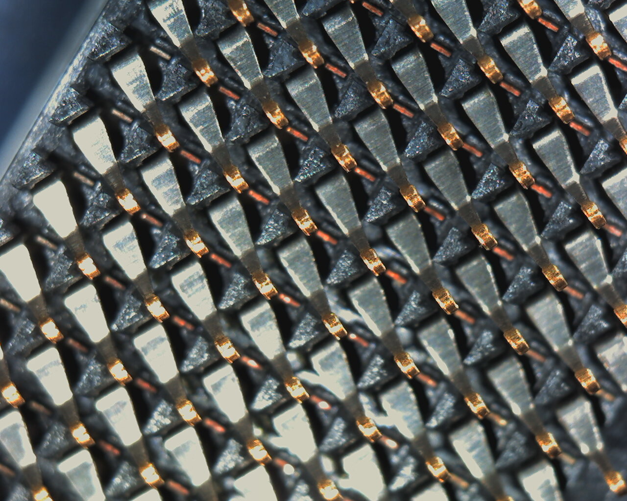
Anytime you are dealing with a LGA socket and missing memory channels, first thing to do is pull the cpu, examine the socket pins for any pins on the outside rows that are out of alignment and then reseat the cpu and wiggle it a bit in the socket before clamping down the retention mechanism. Thanks Keith, I'll give that another try the next time we run out of work. The first time I did that I only checked for bent pins like the MSI support auto-reply states. Socket 1200 must have very tiny pins because I really didn't see them. Next time I'll use loops to examine things. I really appreciate your learned advice. |
|
Send message Joined: 13 Dec 17 Posts: 1424 Credit: 9,189,946,190 RAC: 2 Level Scientific publications |
Anytime you are dealing with a LGA socket and missing memory channels, first thing to do is pull the cpu, examine the socket pins for any pins on the outside rows that are out of alignment and then reseat the cpu and wiggle it a bit in the socket before clamping down the retention mechanism. Yes, I have had issues with both a TR socket and a 2011v-3 socket that wouldn't read all the memory. A wiggle on the TR got it centered on the pins to read all channels. On the 2011v-3 socket I had to move about 8 pins that were out of alignment. A 10X jewelers loupe and strong illumination is best. I use a very bright tactical flashlight shining at low angle across the pins. What you are looking for is any pin ball-tip reflection that is out of alignment in X-Y with the other pins in the row and columns. Then I used a sewing needle to gently nudge the pins back into alignment. Took about an hour and in the end I had all my memory channels reading correctly and the cpu is running well overclocked to this day. |
|
ServicEnginIC Send message Joined: 24 Sep 10 Posts: 595 Credit: 13,083,686,510 RAC: 745,928 Level Scientific publications |
On the 2011v-3 socket I had to move about 8 pins that were out of alignment. A 10X jewelers loupe and strong illumination is best. I use a very bright tactical flashlight shining at low angle across the pins. Fantastic! With socket LGA775 it was much easier. Doing this with 2011 socket is a truly feat... |
|
Send message Joined: 8 Aug 19 Posts: 252 Credit: 458,054,251 RAC: 0 Level Scientific publications |
Okay, so I'm supposed to find the outer rows of pins on the processor and check the alignment with loops under bright light. Next time I reboot to patch my funky windows OS I'll give it a go. This z490 board seems flawless otherwise and with 2 GTX 1650's putting out around 525,000 between them while my i5-10400 crunches 8 threads of WCG tasks, they're averaging close to the 225,000 benchmark that was no doubt set by a Linux machine when rod4x4 surveyed the stats. Guess I shouldn't dis MSI because of my lack of tech savvy. Thanks again. |
|
Send message Joined: 13 Dec 17 Posts: 1424 Credit: 9,189,946,190 RAC: 2 Level Scientific publications |
I did some research on the 2011v3 socket in pin assignments and looked for the pins that handle Channel D. Found what I needed in the Intel Core i7 Processor for LGA2011-v3 Socket document. The section labeled Processor Land Listing showed the pin assignments. That was the document that also listed the maximum deviation of the absolute position of the land grid pins. Which is a lot tighter than I would have expected. Doesn't take much misalignment to have a memory channel go missing. They were in the outer row on the side nearest the VRM heatsink. |
|
Send message Joined: 22 May 20 Posts: 110 Credit: 115,525,136 RAC: 0 Level Scientific publications |
Most NVME SSDs that don't come included with a heatsink usually have a warranty sticker on top. Some manufactures say that their stickers are meant to improve heat transfer as there are apparently woven copper lines in it. While I question that, they also void warranty if the sticker is removed. Now my question, if the mobo comes with included heatsinks for the M2 NVME drives: (1) Should I just install the SSDs as it is without the heatsink? (2) Should I just put the heatsink on top of the sticker? Is this safe to do, in the sense of the heatsinks thermal pad directly touching the SSD's sticker? If removing the sticker would be the way to go in order to properly and safely install the heatsink on top of it, I would probably opt for option 1. Thanks in advance for your input |
|
Send message Joined: 21 Feb 20 Posts: 1117 Credit: 40,876,970,595 RAC: 0 Level Scientific publications |
i just put it over the sticker. 
|
|
Send message Joined: 22 May 20 Posts: 110 Credit: 115,525,136 RAC: 0 Level Scientific publications |
Perfect, so that's what I'll do as well. Thanks! |
|
Retvari Zoltan Send message Joined: 20 Jan 09 Posts: 2380 Credit: 16,897,957,044 RAC: 0 Level Scientific publications |
i just put it over the sticker.+1 |
|
ServicEnginIC Send message Joined: 24 Sep 10 Posts: 595 Credit: 13,083,686,510 RAC: 745,928 Level Scientific publications |
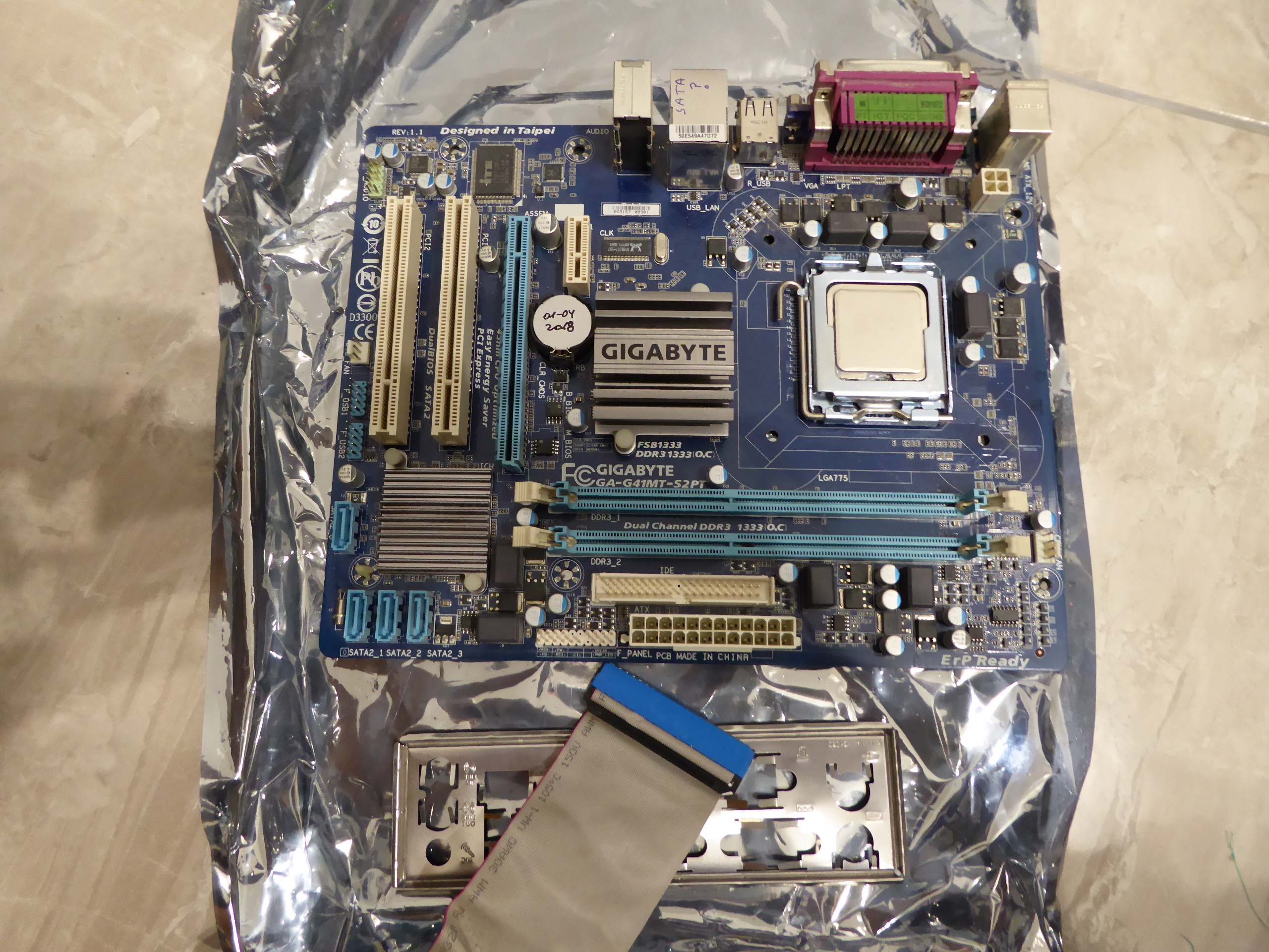
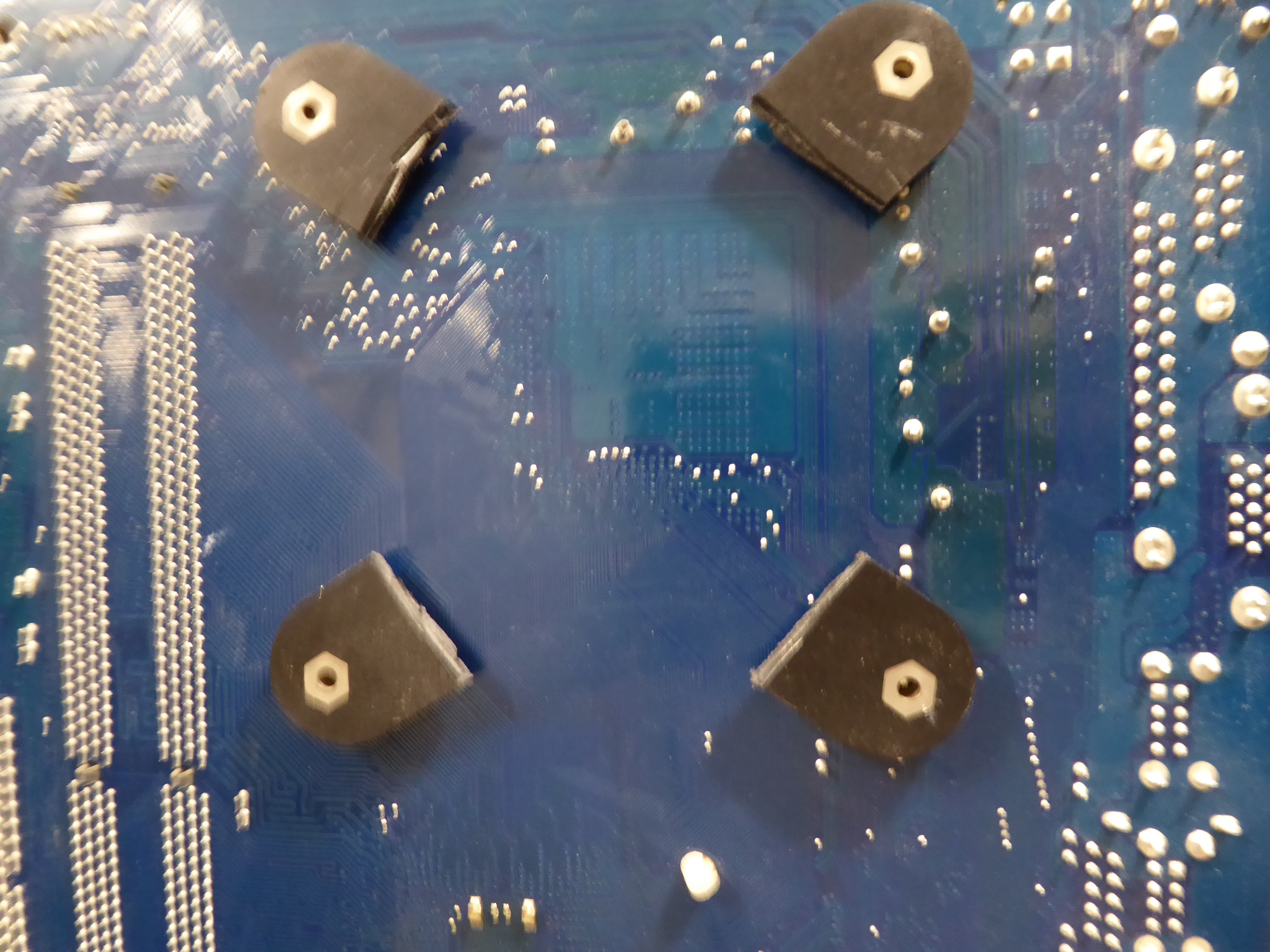
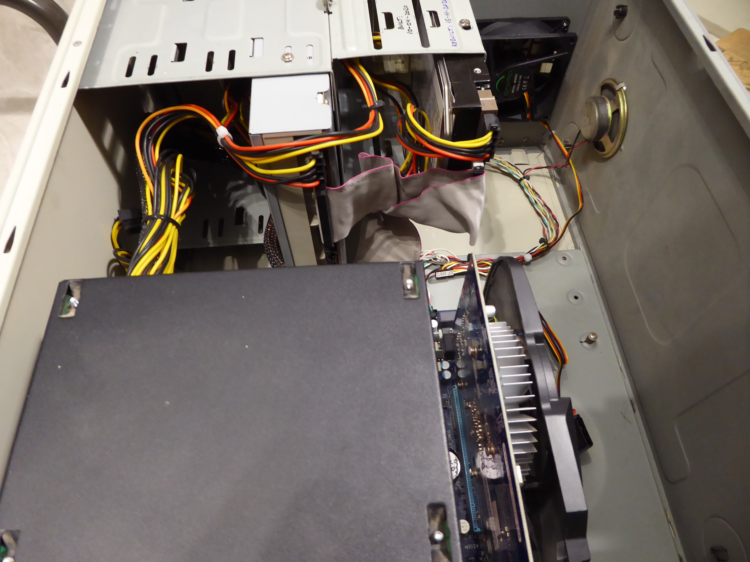
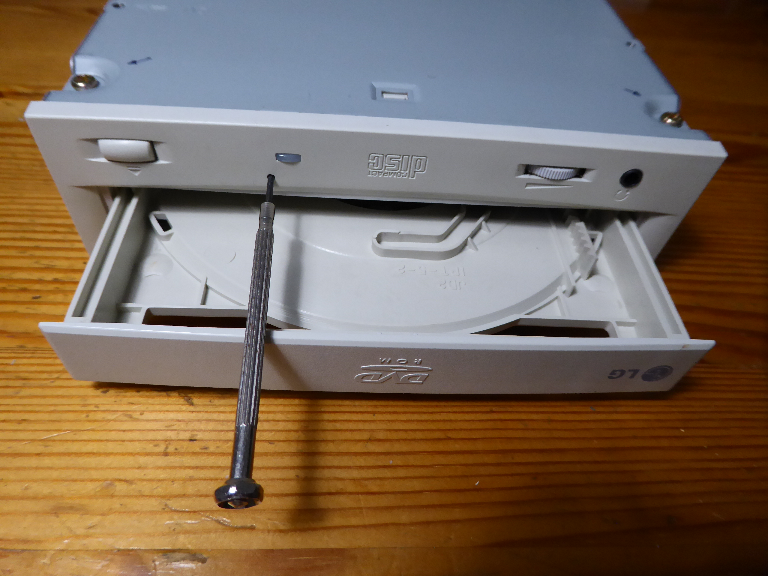
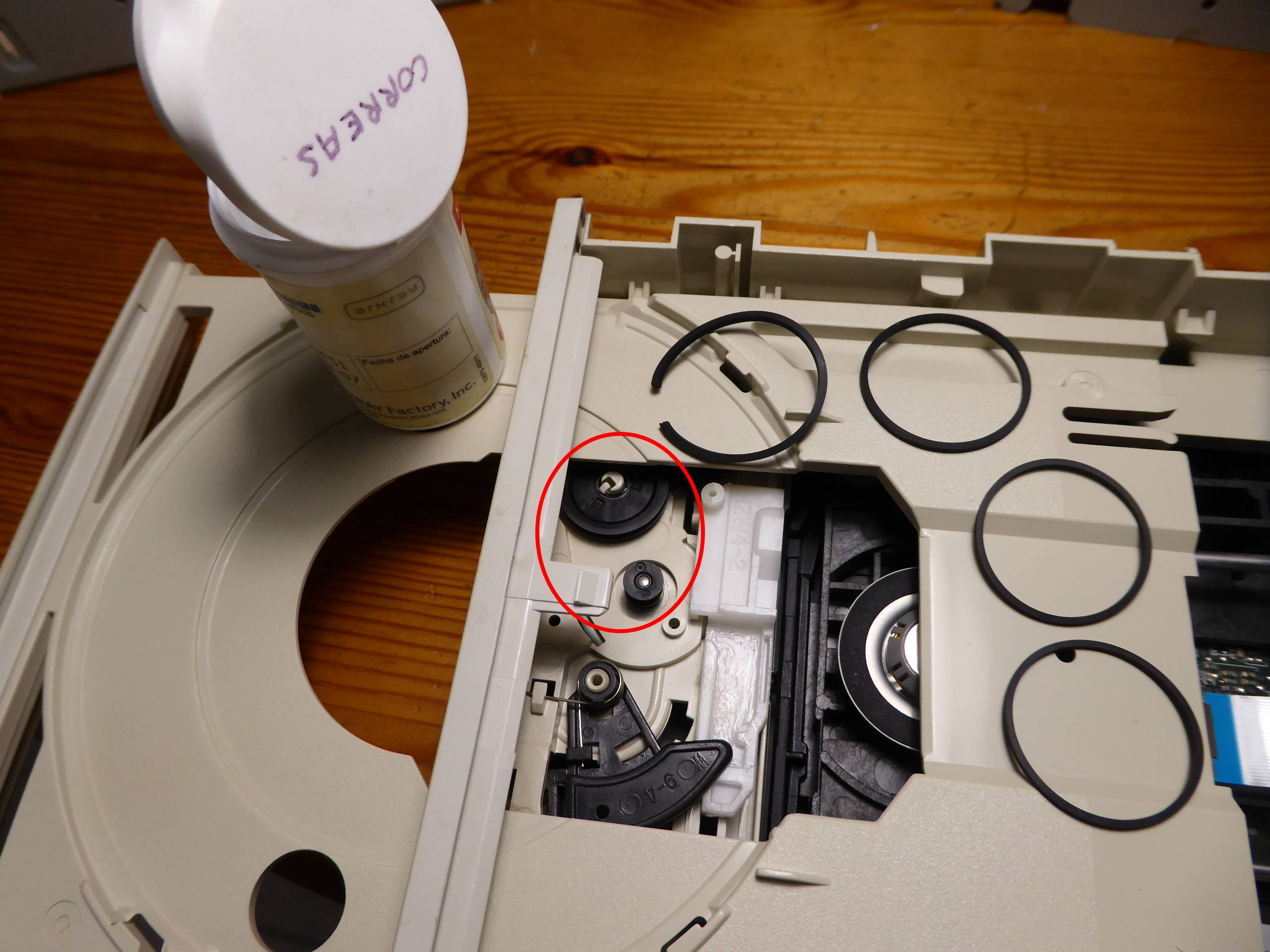
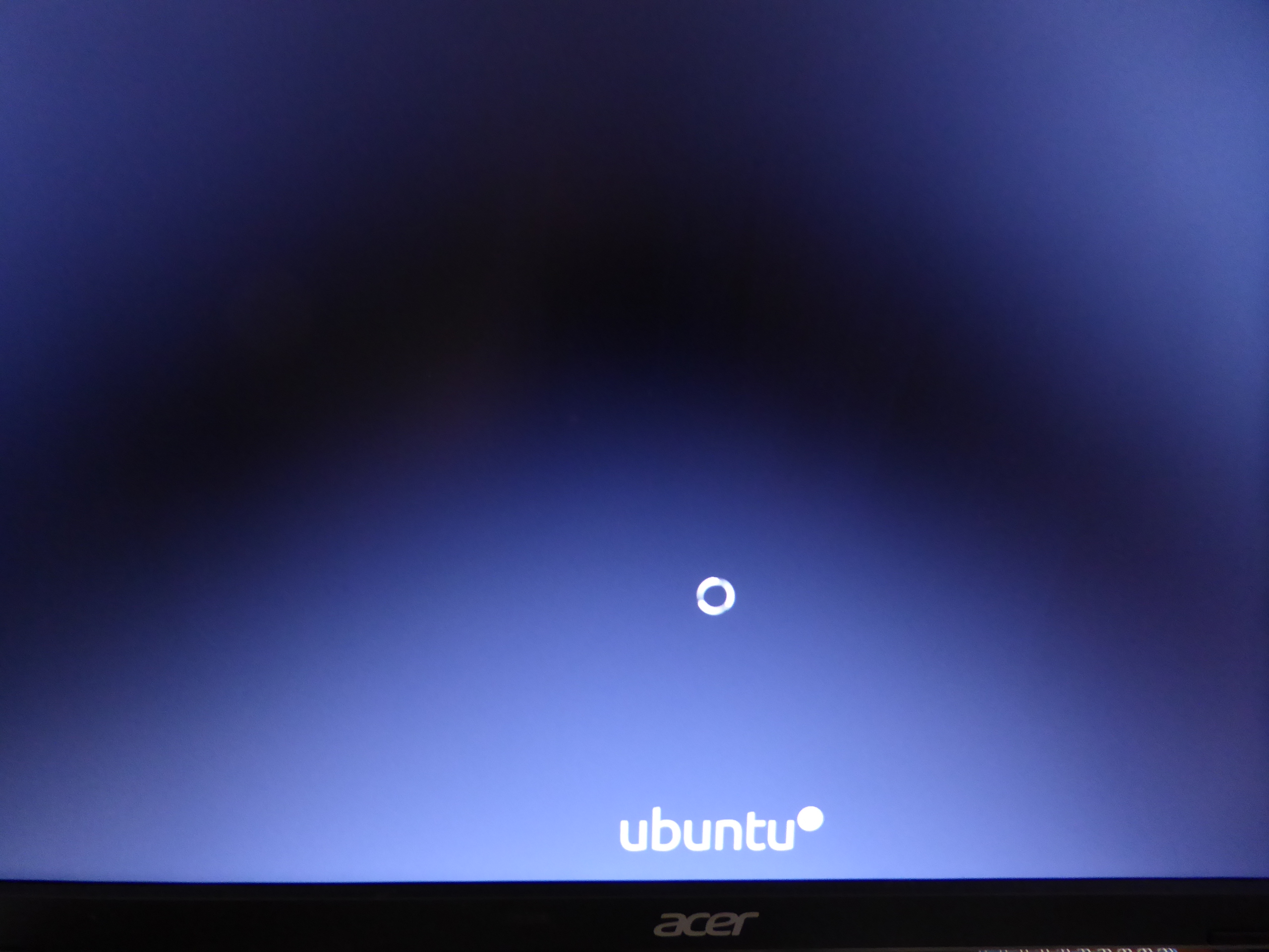
On June 15th 2020 I related How I had to replace motherboard-memory-processor in a system with failing SATA controller. - Cause: Motherboard's SATA controller section failure. The related failing motherboard is this one. But recently I thought: This motherboard has also an integrated IDE controller, will it be still working? The only way to discover it is giving it a try... Ok, I have motherboard, memory and processor. From my fossils wardrobe I rescued: - An old scrapped minitower chassis - An IDE 160 GB hard disk drive and IDE cable - An IDE DVD optical unit and DVD media with Ubuntu 20.04.1 LTS image, dowloaded from Ubuntu official site. - A 600 watts PSU coming from a previous PSU upgrade in a triple GPU system - Two 775 processor copper core heatsinks, discarded due to their fixing backplates were broken - A working GT1030 low power GPU, coming from a GPU upgrade on other system - An ancient Wireless-G PCI network adapter Therefore, I had everything I needed to assemble a "new" host. I first started cutting four healthy backfixings for CPU heatsink, and assembling them into motherboard. Then, a little workmanship and motherboard and peripherals are assembled into chassis. Now, PSU is at position also, just over CPU and adjacent to graphics card in this mini tower compact chassis. Power on! Initial beep sounds, followed by video, entering BIOS setup is successful, and both IDE hard disk and optical unit are recognized. Ok! Time to OS installation. Linux install media is entered into optical unit... but it isn't recognized, and a subsequent try to eject it doesn't work. Well, there is a spanish saying: "Mal comienzo, buen final" ("Bad start, happy ending") Trying with a watchmaker's screwdriver into emergency ejection hole, media platform is out. And taking a look to ejection mechanism pulleys, transmision belt is confirmed to be broken. It is something quite usual, and I like to have spare belts available (spanish "correas") After mounting it back again, now Ubuntu installation media is happily running, and OS installation can be carried on. Was it worth it or not? Now it can be seen working at GPUGrid as host #567828 since november 15th. It has crunched its first million credits with zero errored tasks, and current RAC is over 65000 after 16 days working. This is what I expected to achieve with its 30 Watts TDP low power GPU... I really enjoy giving a second or third life to hardware resources! PS: Due to the diverse provenance of the scrapped parts composing this host, I've called it: "Mr. Frankhostein" ;-) |
|
Send message Joined: 22 May 20 Posts: 110 Credit: 115,525,136 RAC: 0 Level Scientific publications |
Sorry for diverting attention once again away from the recent discussion. Currently I am very confused as to what PSU characteristics are required to be compatible with the B550 Asus Rog Strix Gaming mobos. As far as I understand it, you are supposed to run an 8 pin + 4 pin connector in addition to the standard 24 pin connector powering the mobo. The 8 pin is the usual CPU power connector that supplies the mobo's CPU socket but what is the 4 pin adapter for? The B550 Gaming E/F/F Wifi all seem to have the additional 4 pin connector and I am not sure if the PSU I found on sale today will fit the bill (Corsair RM750i). Am I missing something, or is there really missing a connector to run the mobo (safely)? And many of the researched PSUs seem to be incompatible with them. Is it only additional power needed for extreme overclocking and can be run safely without it or is it a necessary requirement? – The manual of the mentioned mobos labels the referred connectors EATX12V (4+8 pin). Thanks for any advice |
|
Send message Joined: 21 Feb 20 Posts: 1117 Credit: 40,876,970,595 RAC: 0 Level Scientific publications |
the 4-pin is exactly half of the 8-pin connector. most PSUs have the 8-pin actualy break out into 2x4-pin. however, the extra 4-pin is totally unnecessary. you do not have to use it, just the 8-pin is enough. the extra 4-pin is intended to add extra power for extreme overclocking, like using LN2 where you could be pulling huge amounts of power. personally having an 8-pin + 4-pin on a B550 board doesnt make sense. B550 is a more budget lower end board. and the guys who will seriously do extreme overclocking with LN2 aren't going to use a B550 board lol, they will be using a top end X570. it just seems like something the board manufacturers do because it costs them an extra 5 cents to add the 4-pin, to justify marking the board up another $5.
|
|
Send message Joined: 13 Dec 17 Posts: 1424 Credit: 9,189,946,190 RAC: 2 Level Scientific publications |
Every power supply I own is modular. And they all come with at least 3 EATX power cables. (1) 8-pin EATX12V (2) 4-pin EATX12V The extra 4 pin EATX cable is usually intended for multi-gpu usage. The reason is to reduce as much as possible the 12V current draw being supplied by the standard 24-pin EATX motherboard cable. Plenty of stories about burning up the 24 pin cable when running all possible PCIE slots with high powered gpus when you don't have auxiliary 12V power being supplied. |
|
Send message Joined: 22 May 20 Posts: 110 Credit: 115,525,136 RAC: 0 Level Scientific publications |
Thank you both for your explanations! Much appreciated. however, the extra 4-pin is totally unnecessary. you do not have to use it, just the 8-pin is enough. the extra 4-pin is intended to add extra power for extreme overclocking, like using LN2 where you could be pulling huge amounts of power. The extra 4 pin EATX cable is usually intended for multi-gpu usage. The reason is to reduce as much as possible the 12V current draw being supplied by the standard 24-pin EATX motherboard cable. So in essence, could I summarise your replies as following: It is generally safe to run B550 mainstream chipset boards without the extra 4 pin connector as long as I am not planning to run all PCIe Slots with high-end GPUs, however it is not disadvantageous if I were to run it with the 4 pin EATX 12V connector in addition to the 8 pin EATX 12V connector to the CPU but rather avoid unnecessary strain on the PSU? Definitely not in the league of LN-cooling Ian, lol it just seems like something the board manufacturers do because it costs them an extra 5 cents to add the 4-pin, to justify marking the board up another $5.That definitely sounds like something that hardware producers would do... In the end I opted for a mainstream chipset board, that for IMO was the right balance between features and price. The Asus Strix B550 -E Gaming still offers to 2x gen4 x16 slots that run in dual x8 mode. The rest is pretty much standard for mainstream retail boards, and the price premium of nearly 50% over "higher-end" mainstream B550 boards was not justified for me personally. This is pretty much I will require for the foreseeable future. In addition, I didn't like that the X570 boards all require active cooling for the chipset, which is an additional source of noise and point of failure. For my first build, I really wanted to go with cost efficient components. While it appears that the mentioned PSU actually had only 1x 8-pin EATX12V connector for their version prior to 2018, I checked my PSU shortlist against what you just taught me, and I can now confirm with you that most of the modern PSUs actually do come with the very same split that you pointed out Keith. (1) 8-pin EATX12V Is ATX12V a connector standard evolution of the EPS12V connector? I saw these names interchangeably in various manuals and wondered whether they are the same or compatible. |
|
Send message Joined: 21 Feb 20 Posts: 1117 Credit: 40,876,970,595 RAC: 0 Level Scientific publications |
it won't hurt anything to plug it in if you have it. if you don't have the extra connector, don't worry about it, you don't need to replace the PSU just for that connector.
|
|
Send message Joined: 13 Dec 17 Posts: 1424 Credit: 9,189,946,190 RAC: 2 Level Scientific publications |
Is ATX12V a connector standard evolution of the EPS12V connector? I saw these names interchangeably in various manuals and wondered whether they are the same or compatible. They are used interchangeably but actually have different origins. The EPS12V standard came out of the Server Standard Infrastructure group. It has a 24-pin ATX motherboard connector (same as ATX12V v2.x), an 8-pin secondary connector and an optional 4-pin tertiary connector. Rather than include the extra cable, many power supply makers implement the 8-pin connector as two combinable 4-pin connectors to ensure backwards compatibility with ATX12V motherboards. The ATX12V standard came out of the ATX group. Most common PC's and motherboards are built to ATX standards so they should get coupled with ATX power supplies. Read through the power supply section of the ATX wiki. https://en.wikipedia.org/wiki/ATX#ATX_power_supply_revisions And there is an upcoming transition called ATX12VO that removes all of the voltages except for 12V from the motherboard main connector and replaces the 24 pin connector with a 10 pin one. |
|
Send message Joined: 22 May 20 Posts: 110 Credit: 115,525,136 RAC: 0 Level Scientific publications |
Very enlightening! Thanks, even though I feel a bit stupid now as I had the very same article opened this morning ... Old habit to search the wiki article in German first even though the English versions tend to be much better organized. Thanks again for the short 101 of PSU connectors :) |

©2026 Universitat Pompeu Fabra