The hardware enthusiast's corner
Message boards :
Number crunching :
The hardware enthusiast's corner
Message board moderation
Previous · 1 · 2 · 3 · 4 · 5 · 6 · 7 · 8 . . . 16 · Next
| Author | Message |
|---|---|
 Retvari Zoltan Retvari ZoltanSend message Joined: 20 Jan 09 Posts: 2380 Credit: 16,897,957,044 RAC: 0 Level Scientific publications |
You are probably right.This is very strange. I didn't experienced such change in the liquidity of the Conductonaut... My Gigabyte AORUS GTX 1080 Ti showed the same symptoms (its GPU temperature rose to 90°C). First I cleaned its fins, but there were no change in GPU temperature, so I reduced its power target to 150W until I could remove the card again for disassembly. After I did, I've noticed that the TGC has solidified, and completely gone from the silicone of the GPU chip. So I re-applied some TGC on both surfaces, and assembled the card. Now it's running fine again (71°C). I regularly check the temperatures of my GPUs, so I'm sure that this change in the physical state of TGC was quite sudden. However I have a GTX 2080 Ti with a copper heatsink, and it's running fine. Other cards with nickel(?) heatsinks and TGC are running fine. I keep an eye on them, if another one will have higher temperatures I'll disassemble that card too. |
|
ServicEnginIC Send message Joined: 24 Sep 10 Posts: 595 Credit: 13,083,686,510 RAC: 745,928 Level Scientific publications |
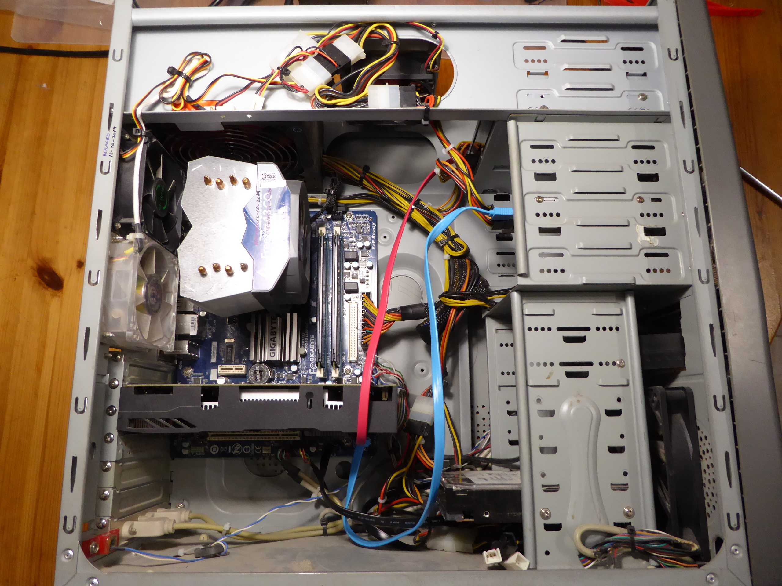
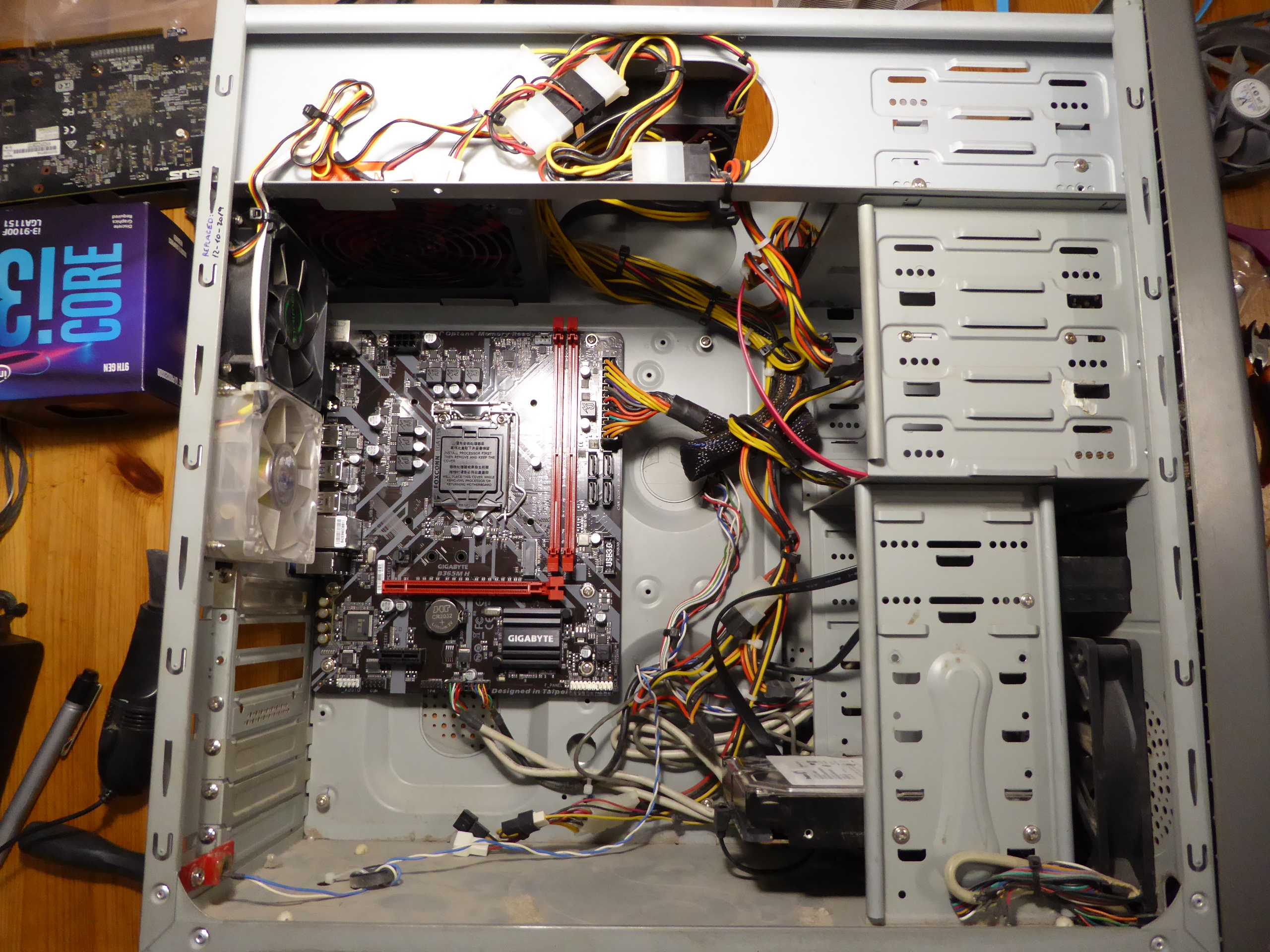
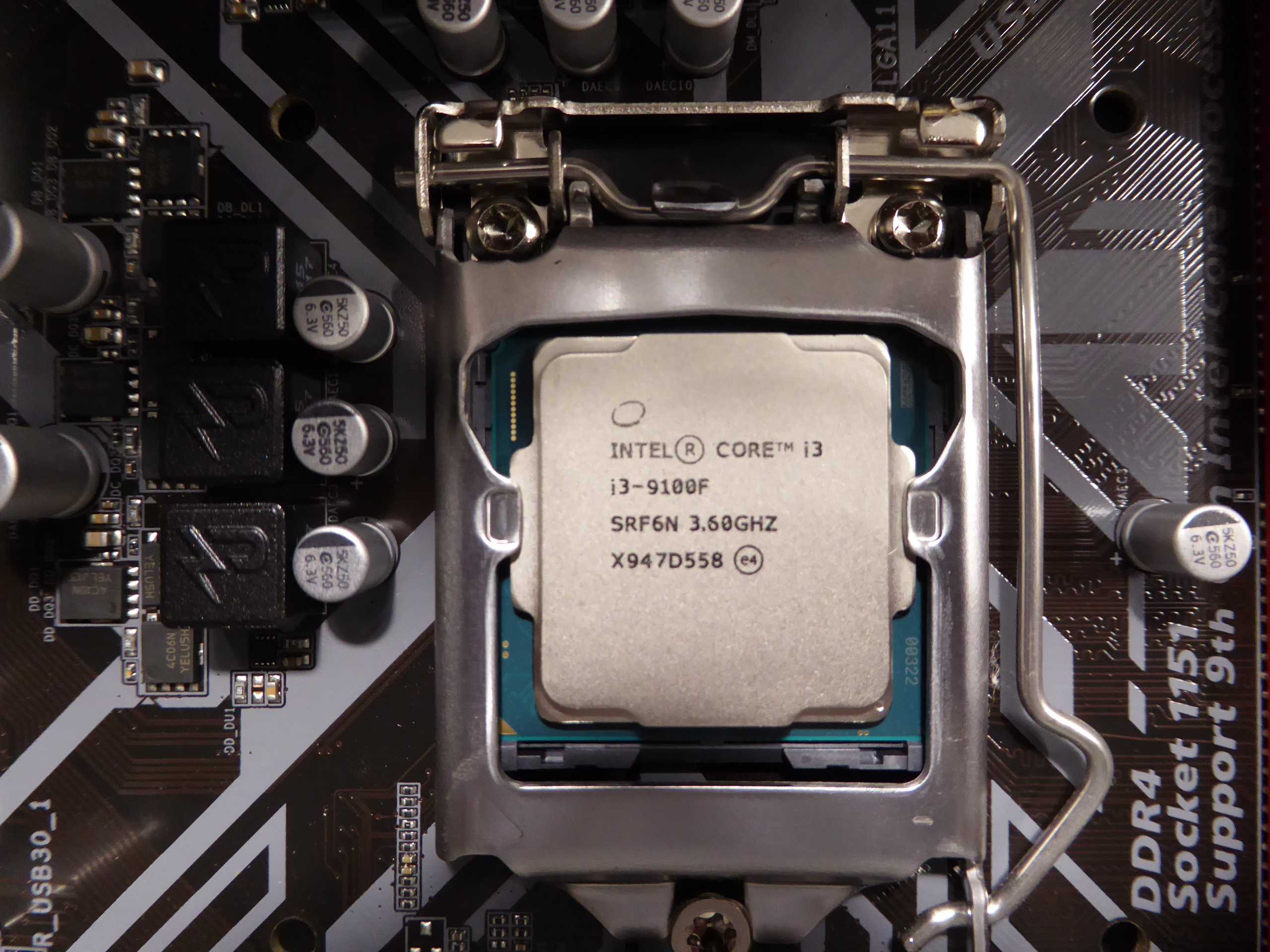
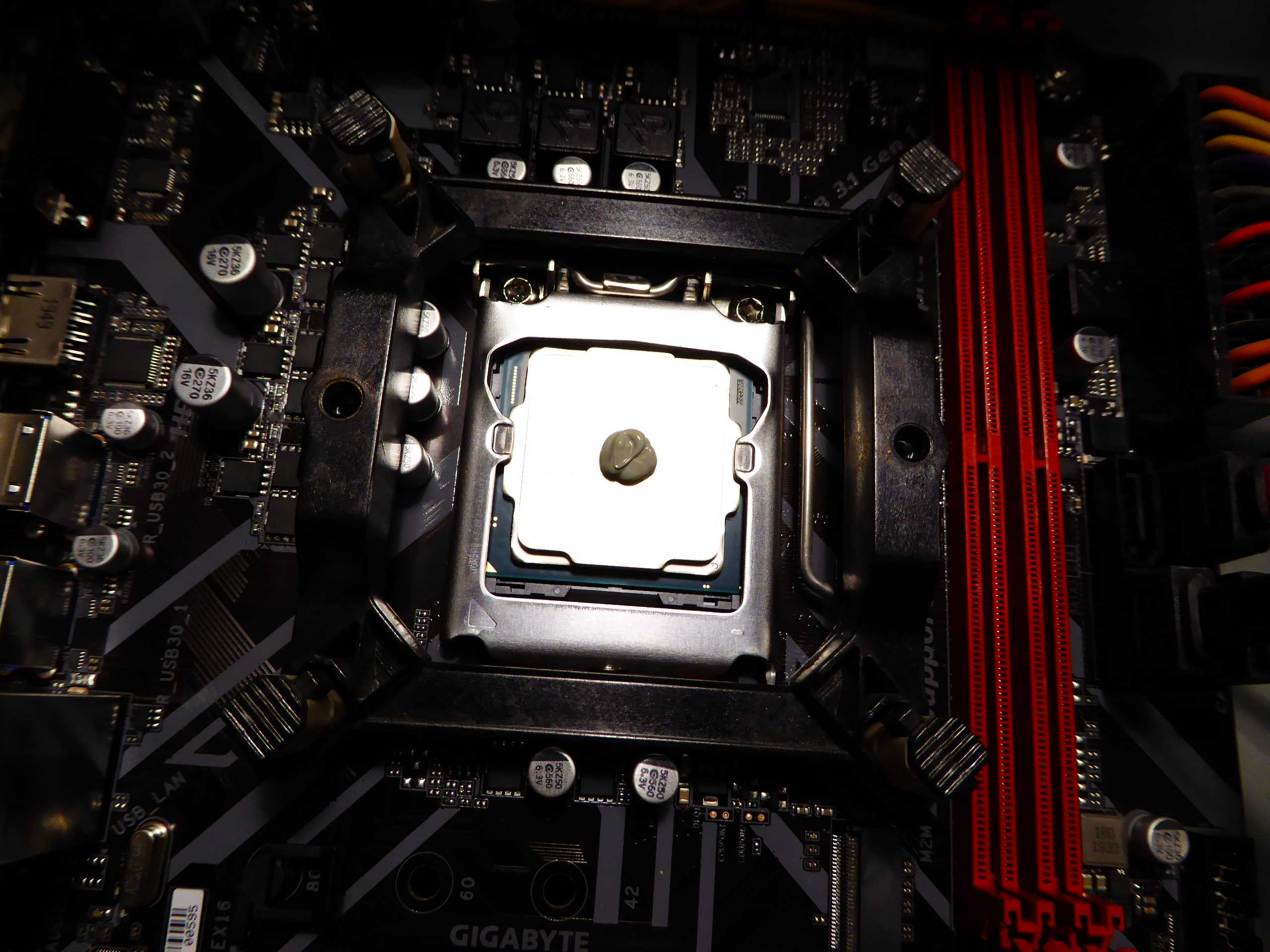
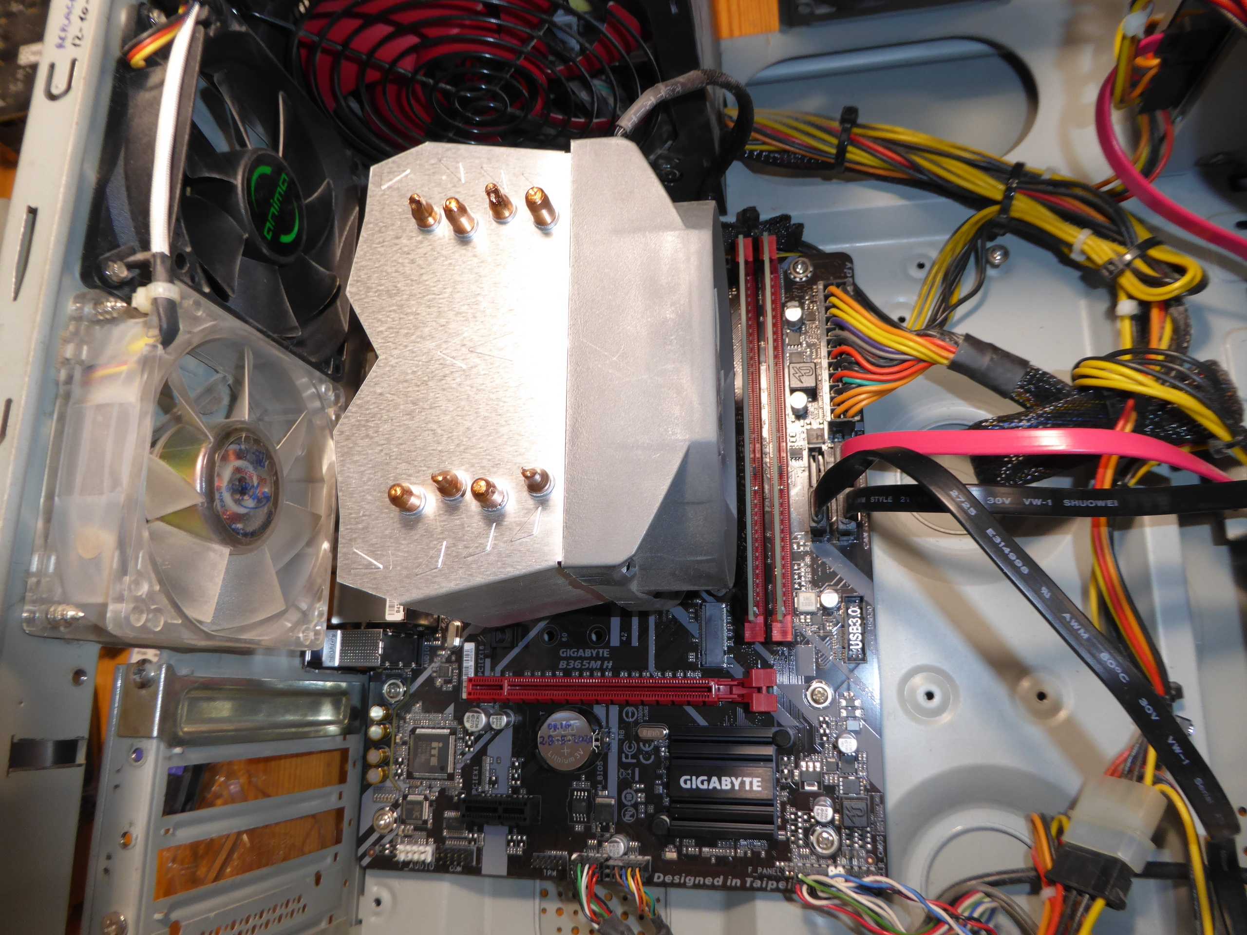
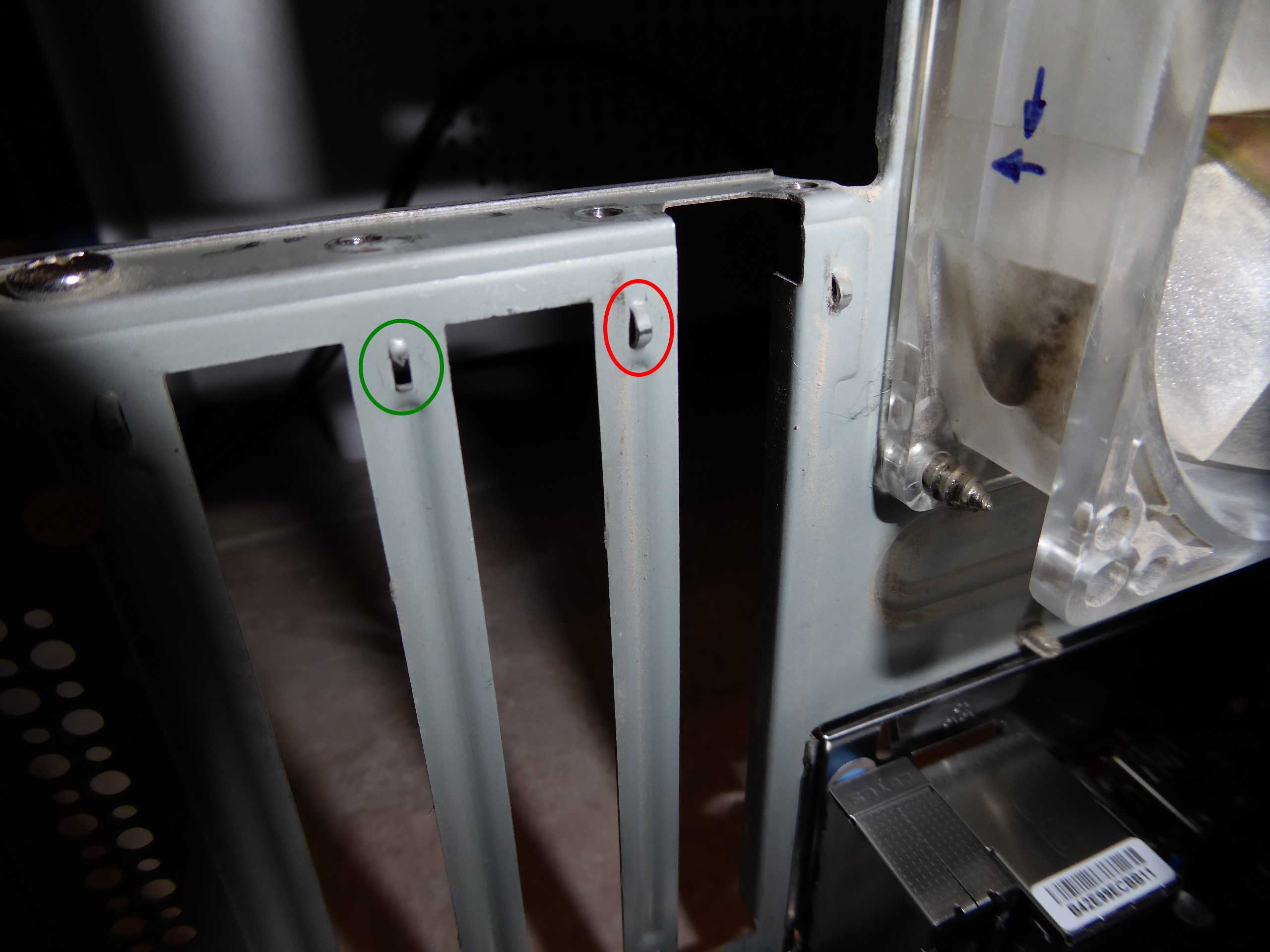
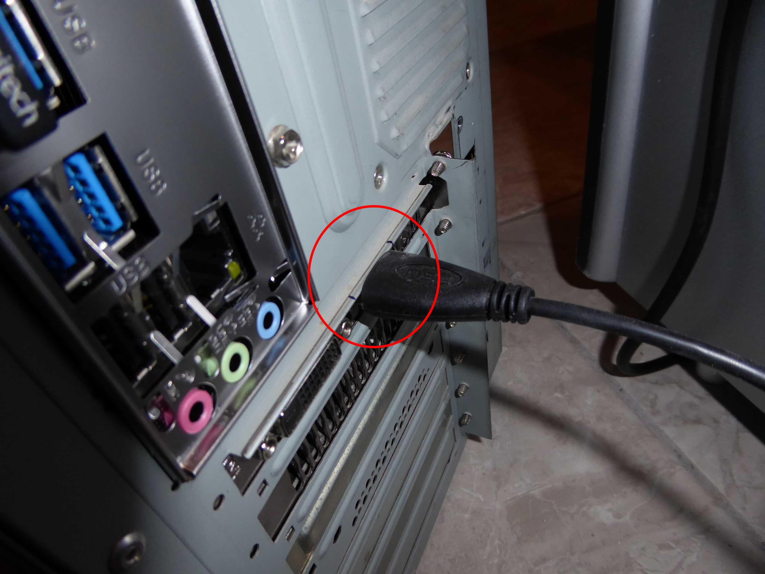
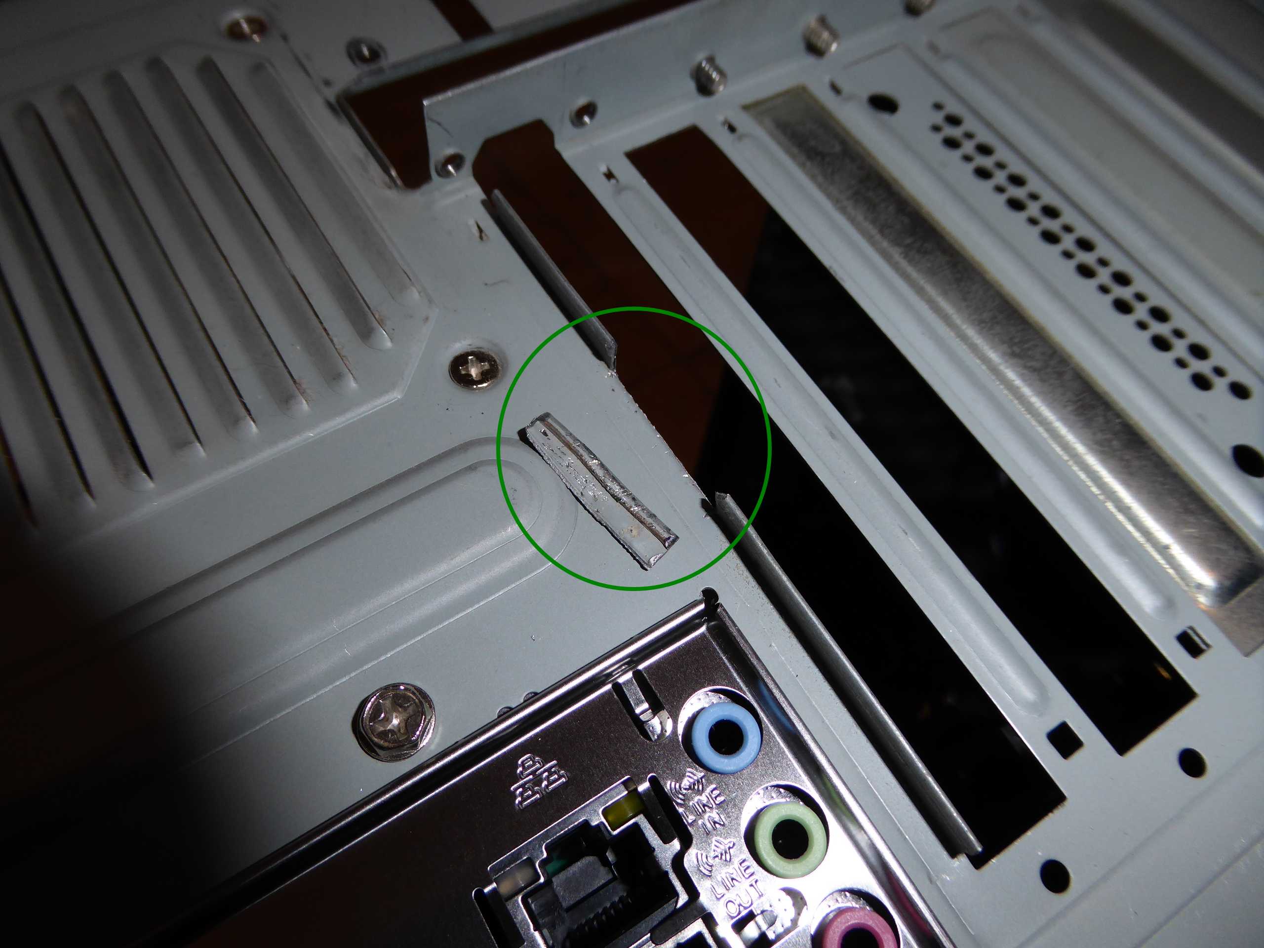
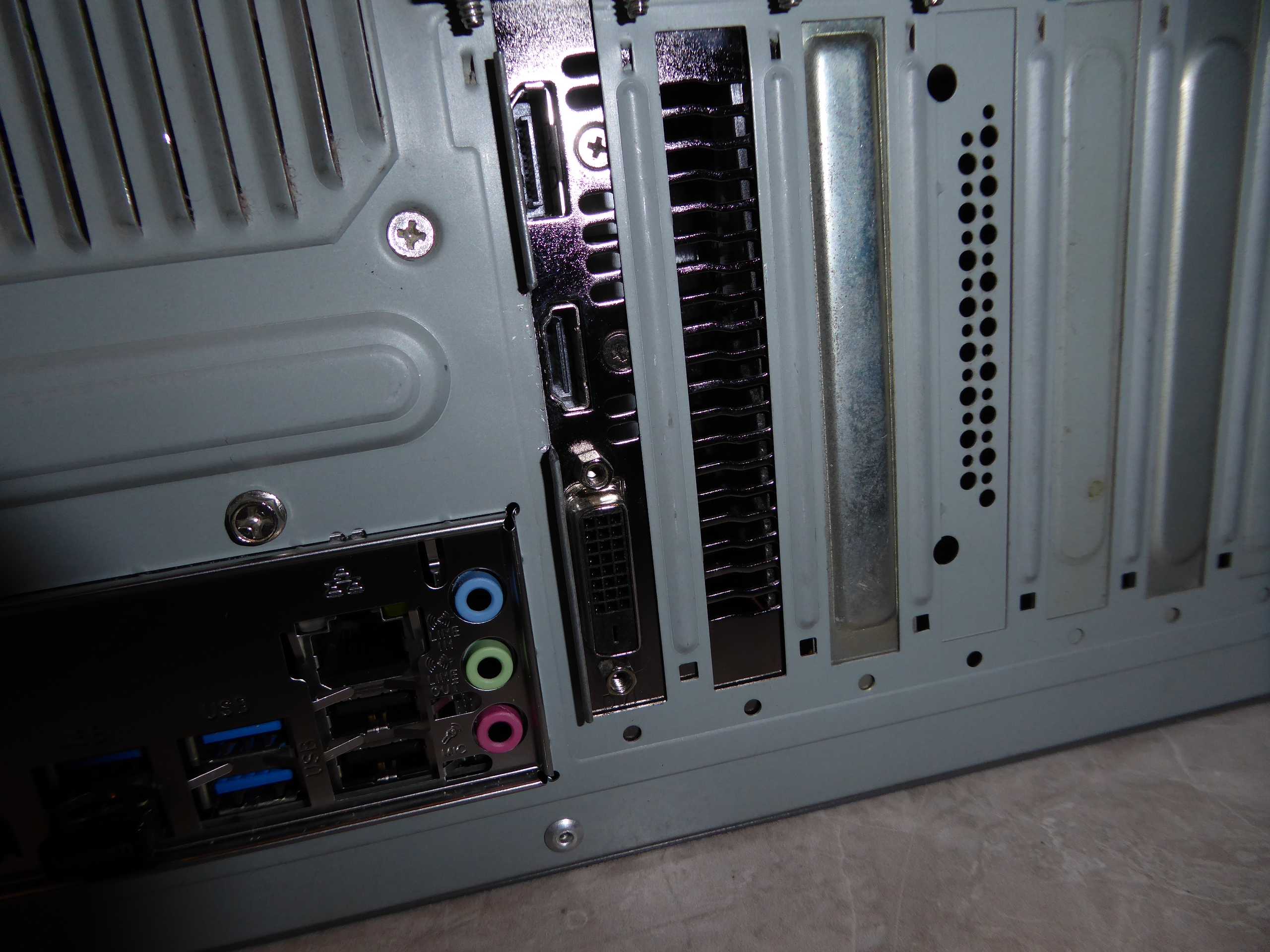
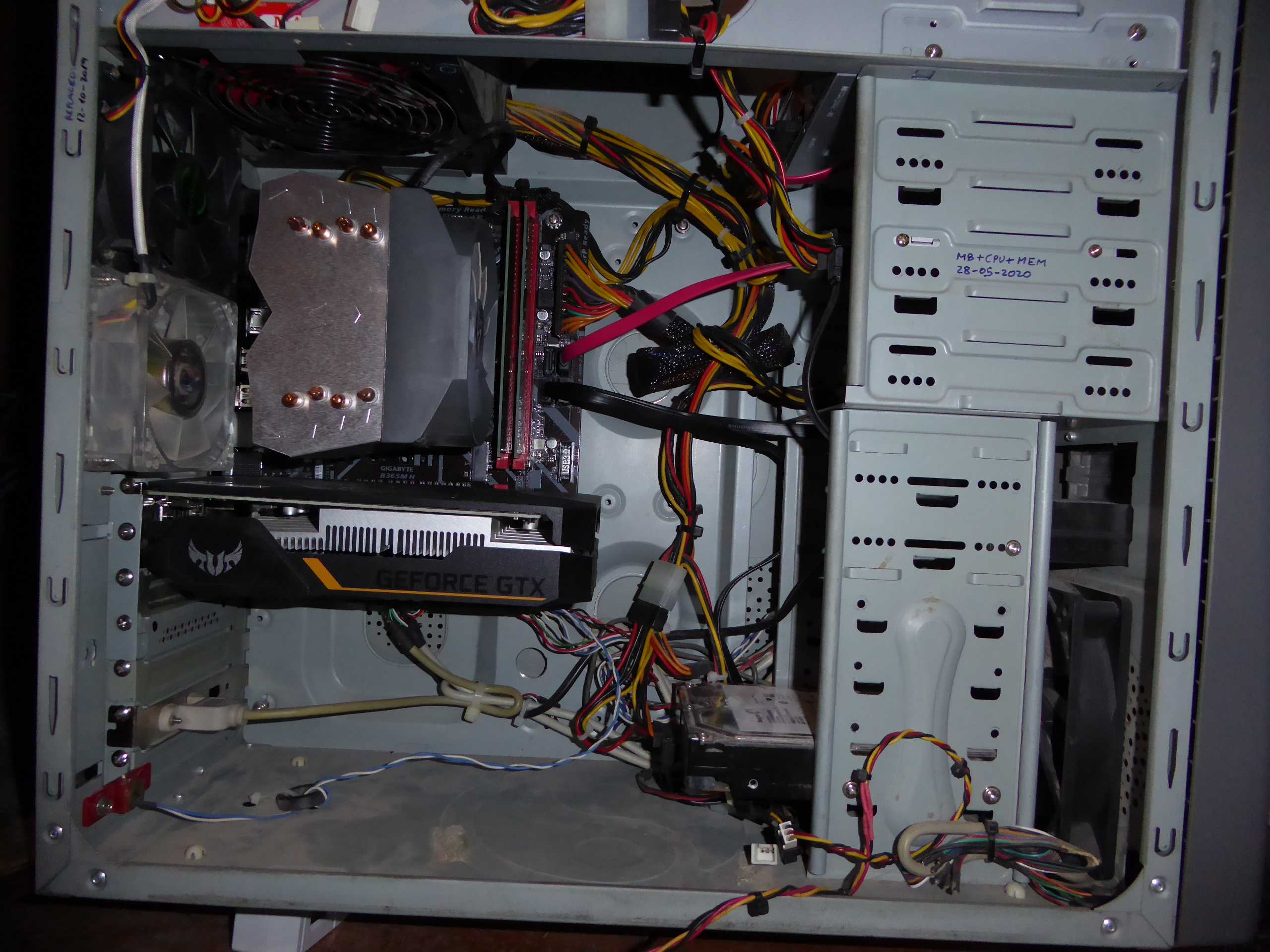
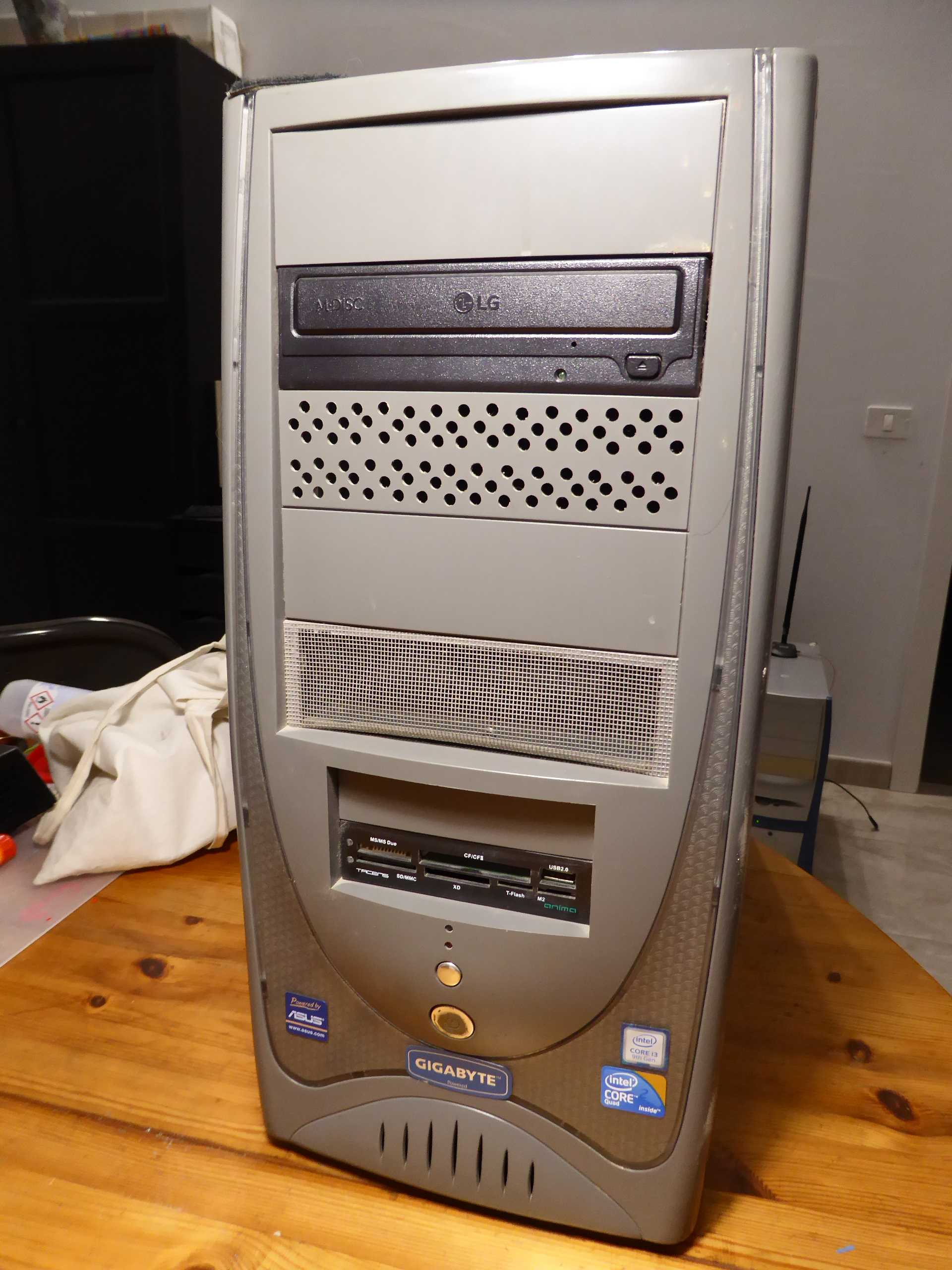
I'm pleased to return to posting, after a forced silent period: my main computer crashed (the same computer I'm writing this from), and I had to recover it first. Good opportunity to tell some curiosities regarding this... It is a permanently working/crunching Ubuntu Linux + Windows 10 OS computer. I usually stop it only for some preventive maintenance from time to time. - Symptoms: On first day I found this computer was blocked in the morning, not responding to keyboard or mouse. I restarted it, and apparently it returned to normality. On second day, I found it had blocked again, but when I restarted it and Ubuntu was booting, a black screen with multiple errors regarding hard disk access appeared. I did a hard stop by pressing power switch, then I checked all HDD SATA and power cables. After rebooting, the Ubuntu HDD was not recognized, and system tried to boot from Windows 10 HDD, but It failed. A new connections check, but in a subsequent reboot no SATA devices were recognized: nor Ubuntu HDD, nor Windows 10 HDD, nor SATA optical unit (CD/DVD writer). - Cause: Motherboard's SATA controller section failure. - Solution: Motherboard replacement. Starting from a veteran system with motherboard for Socket 775 processors and DDR3 memory, replacing motherboard by a current one implies also to replace CPU and RAM. Old system. New motherboard installed. Installing CPU. Applying self-spreading thermal paste. CPU heatsink and DDR4 memory modules installed. Now I decided to replace the previous Pascal GTX1050Ti graphics card by a Turing GTX1650 one. This card was not recognized on old motherboard... Every cloud has a silver lining! But I found a mechanical problem due to some chassis slot separators protruding inwards, and preventing the new card to seat properly. I Cut them with a sharp wire cutter, as seen in red (before cutting) and green (after cutting). Once the graphics card was properly seated , a new problem arose: again, one inopportune chassis flap was preventing the HDMI connector to enter its socket. Cutting some space in the flap and bending it back and forth with a cable plier did the trick. This is the inside of the "new" system, and this is the outside.. In some way, a retro look that I like. These are this new Ubuntu OS System characteristics: And this is the same system on its Windows 10 side: At this point, a... let's say... new problem: When starting Windows 10, one message was shown indicating that too many changes had been detected in computer's hardware. And thus, the old OEM Windows 10 license was no more valid on this "new" system. I had to buy a new license to reactivate my Windows 10 copy... And now everybody are happy: Microsoft and me ;-) |
|
ServicEnginIC Send message Joined: 24 Sep 10 Posts: 595 Credit: 13,083,686,510 RAC: 745,928 Level Scientific publications |
A very specific problem, with a simple preventive action: - Specific conditions: 24/7 working computer, with Linux (Ubuntu) operating system, and communications based on a WiFi network interface. - Symptom: From time to time, WiFi connection is lost, thus preventing BOINC Manager to report completed tasks and ask for new ones. - Specific cause: WiFi network interface entering power saving mode. - Specific solution: Deactivate WiFi network interface power management, for it to be always active. The way I use to achieve this: -1) Enter a Terminal window -2) Enter command sudo iwconfig -3) Something like this is obtained: wlx031415926536 IEEE 802.11 ESSID:"WLAN_PI" -4) Watch at the line "Power Management". If it is indicated to be off, the problem is probably due to other reasons. If it is on: -5) Type command sudo gedit /etc/rc.localto edit rc.local file. -6) Add the line iwconfig wlx031415926536 power offimmediately before the last line. Note that the string "wlx031415926536" must be equal to the one starting the list obtained in step 3. -7) The resulting file would look as follows: #!/bin/sh -e -8) Save changes to rc.local file and reboot. After following theese steps, when entering the same command than in step 2, the answer would look something like this: wlx031415926536 IEEE 802.11 ESSID:"WLAN_PI" Note that Power Management now is off. And if so, WiFi network interface will remain always active. |
|
ServicEnginIC Send message Joined: 24 Sep 10 Posts: 595 Credit: 13,083,686,510 RAC: 745,928 Level Scientific publications |
Another recurrent hardware problem to be mentioned: It may cause intermitent read/write troubles on SATA units, and even system to get randomly frozen due to this. The reason is a progressive deformation in SATA power connectors, causing an eventually bad electrical contact and subsequent power transients on SATA unit. It can be seen at the following image: 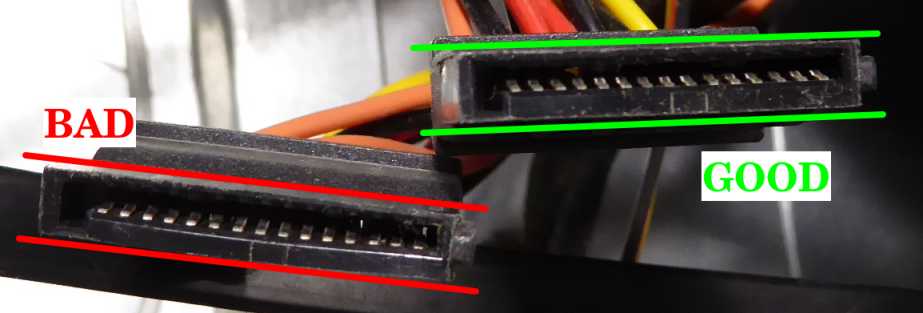 A good connector will show a perfect paralelism on its two longitudinal sides A bad connector is usually widened at its central zone, causing it to look like a couple of "parenthesis symbols" ( ) Please, don't trust a connector like this if you want to avoid misterious problems... |
|
ServicEnginIC Send message Joined: 24 Sep 10 Posts: 595 Credit: 13,083,686,510 RAC: 745,928 Level Scientific publications |
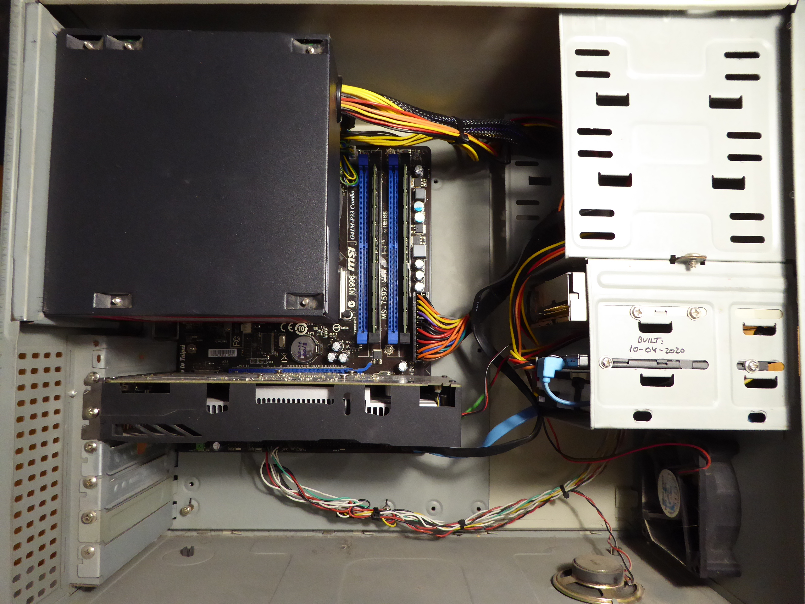
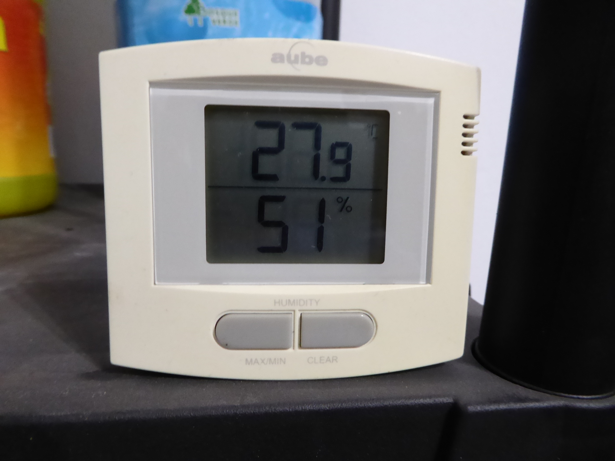
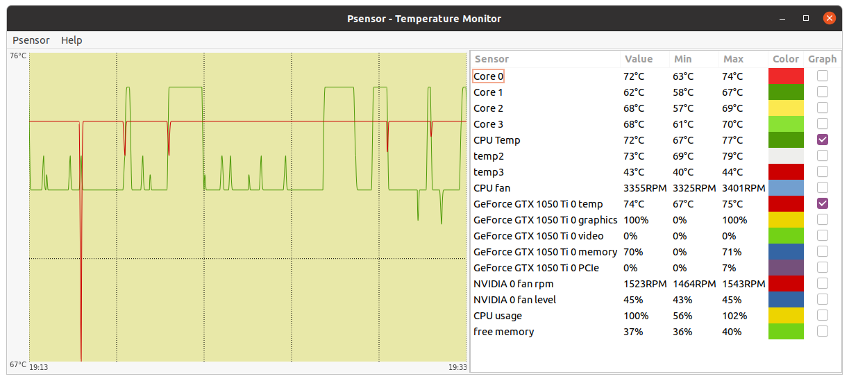
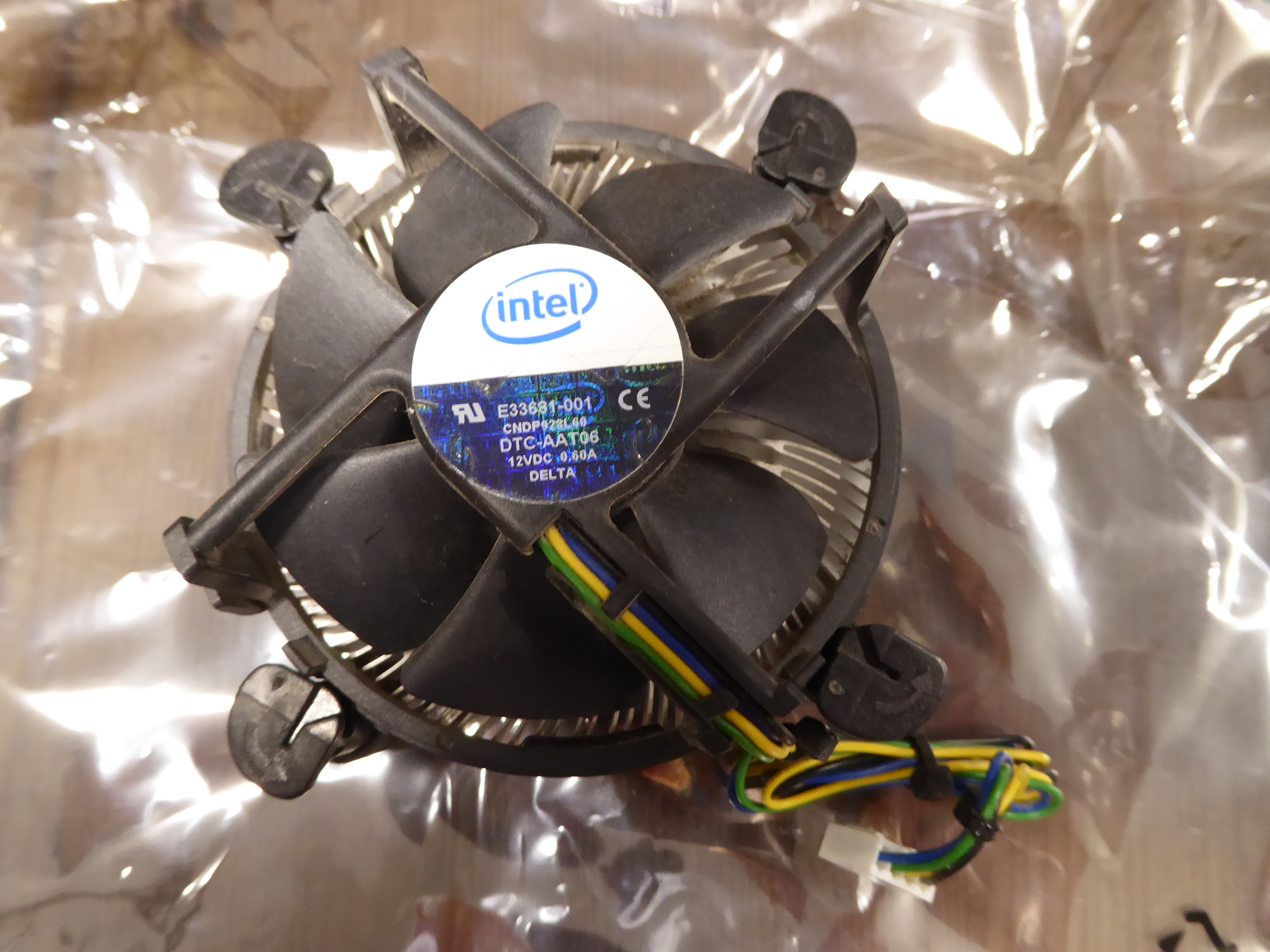
Now, a very disturbing temperature problem, demonstrating the importance of proper refrigeration: It was observed at this system It was mounted in an old ultracompact minitower case, as seen at this picture. CPU cooler was an Intel stock low profile one. And PSU was mounted directly over it. Room temperature: (Canary Islands summer) arround 28 ºC At this situation, Psensor readings were as follows: As can be seen at Psensor image - CPU temp peaked 77 ºC CPU maximum case temp is rated 76,3 ºC, as stated in Q9550S CPU datasheet. - temp2 (Chipset Temp) peaked 79 ºC... Too hot for my peace-of-mind ! Intel stock CPU cooler is a passive one, irradiating CPU heat all arround, including nearby Chipset's heatsink... - CPU cooler's fan was turning at 3355 RPM: It sounded like a drone ready to take off. Then, I had the chance to get an scrapped extra-wide PC tower case. And I rescued from my spares drawer an old Gigabyte G-Power II Pro CPU cooler It is a good heat-pipe based CPU cooler. It was at drawer because... It only seats at extra-wide PC cases :-) And now, the same system after reinstalling it in a wider, better vented case, plus new CPU cooler, reaches the following temperatures: As can be seen at new Psensor image - CPU temperature peaks at 50 ºC (27 ºC less than before, at the same room temperature) - Chipset temp peaks at 63 ºC (16 ºC less than before) - New CPU cooler's bigger fan is turning at 1675 RPM... Half the previous speed, and much quieter Now, I can go happily to drink a fresh lemonade... 🤗️ |
|
ServicEnginIC Send message Joined: 24 Sep 10 Posts: 595 Credit: 13,083,686,510 RAC: 745,928 Level Scientific publications |
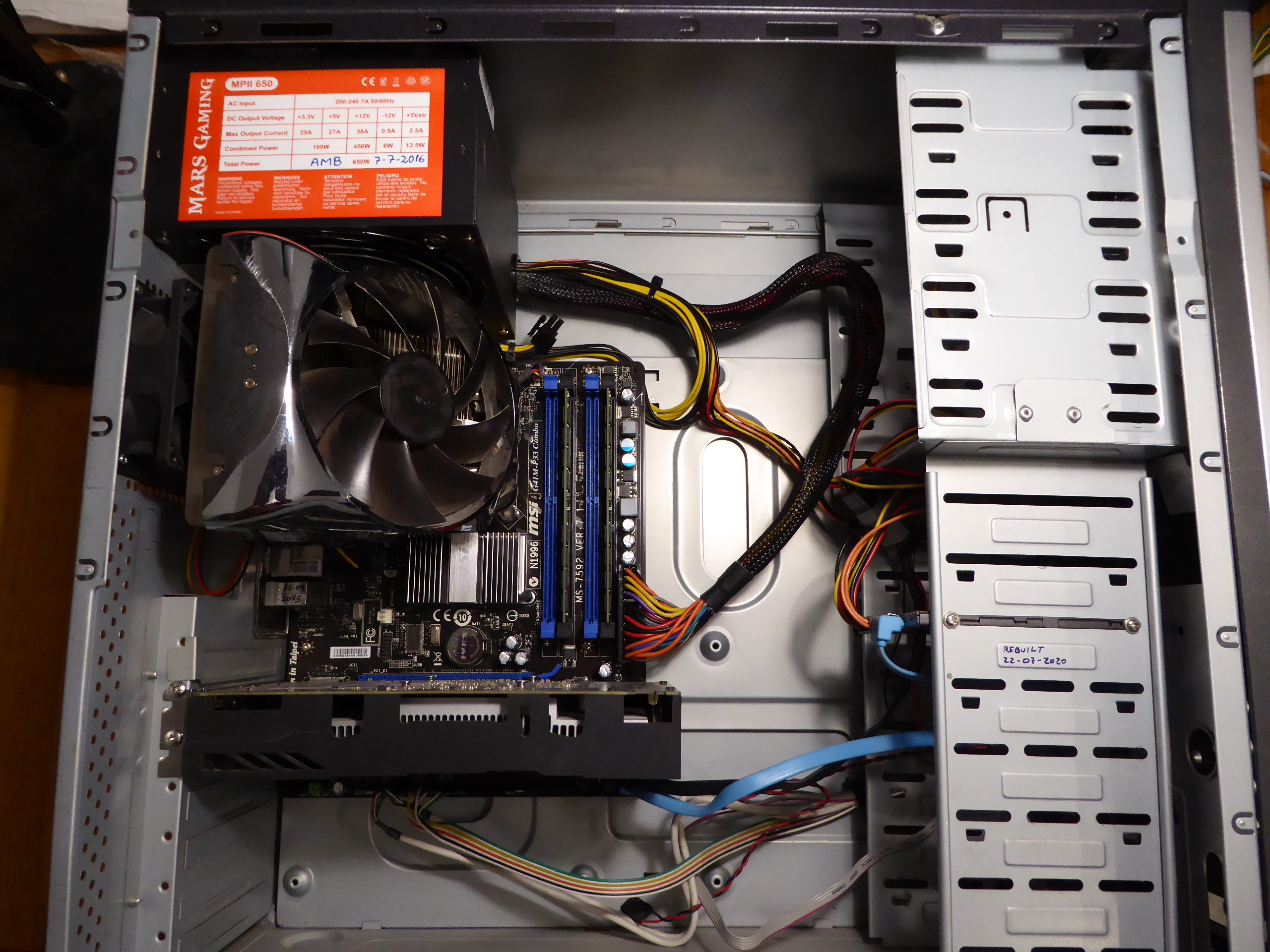
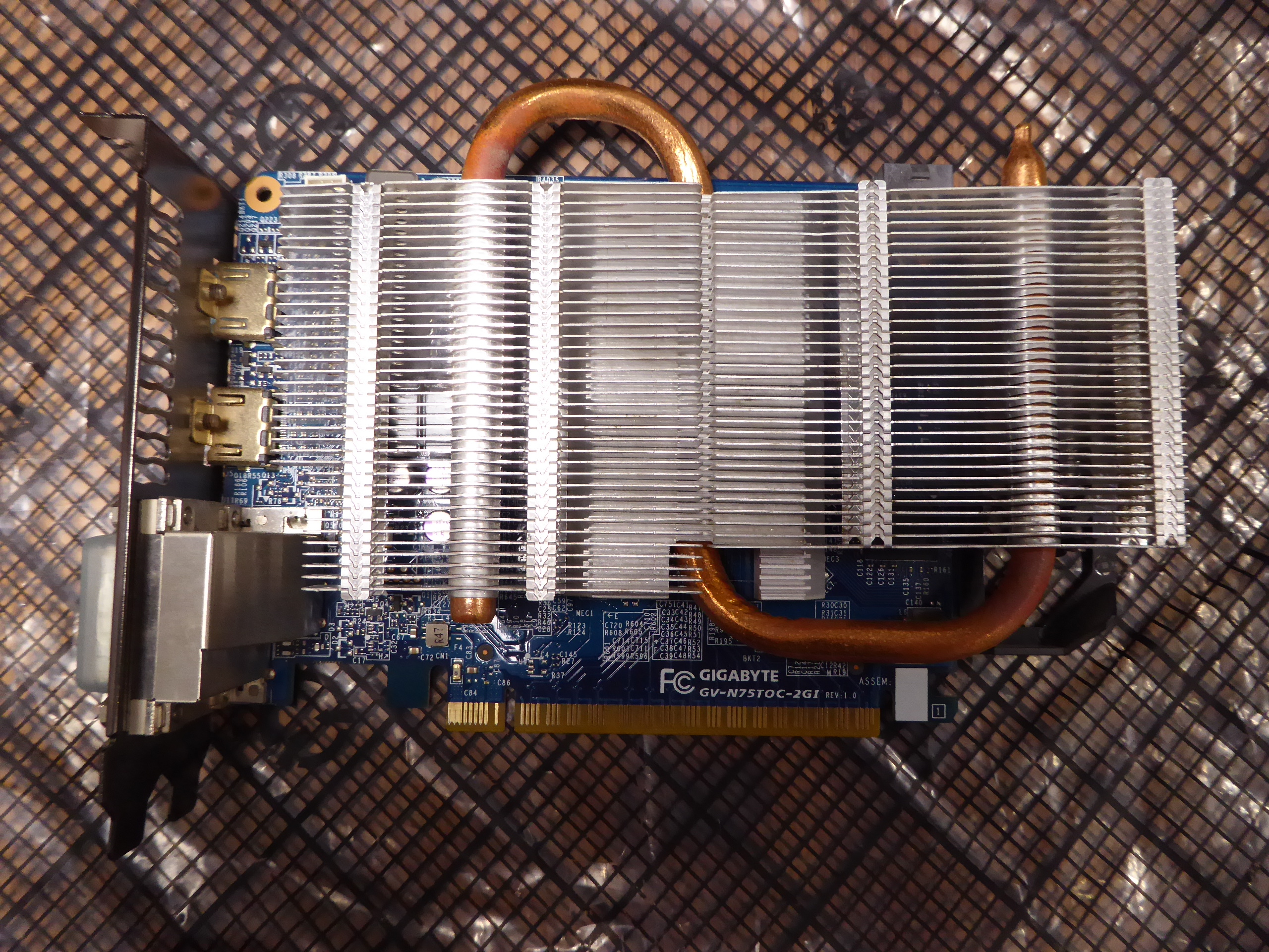
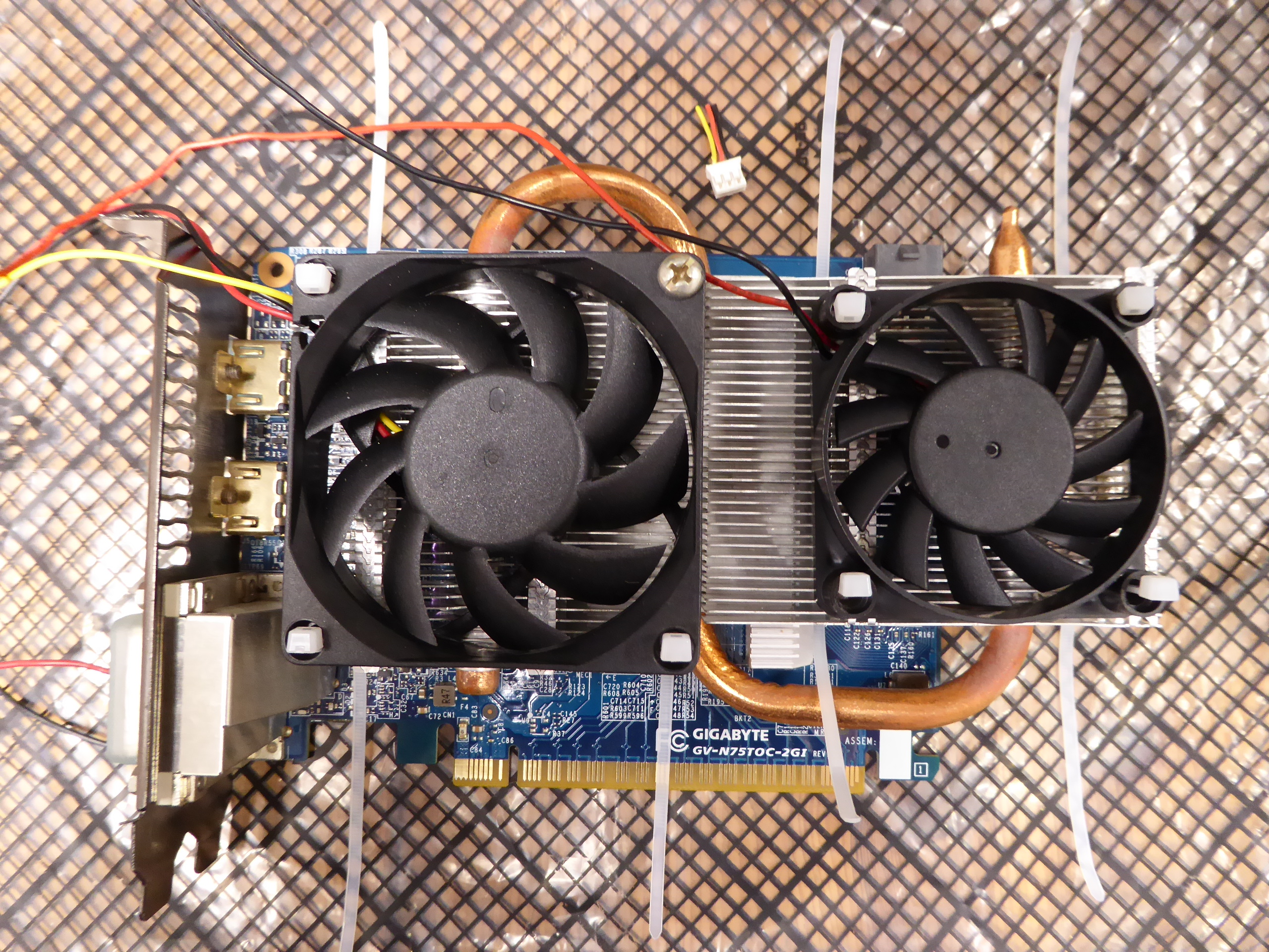
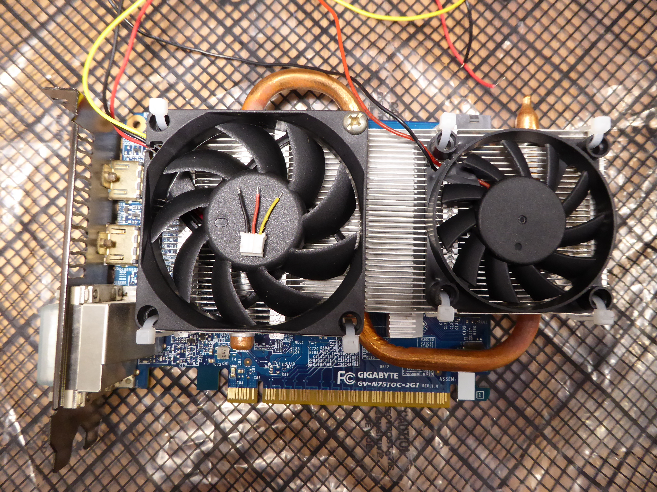
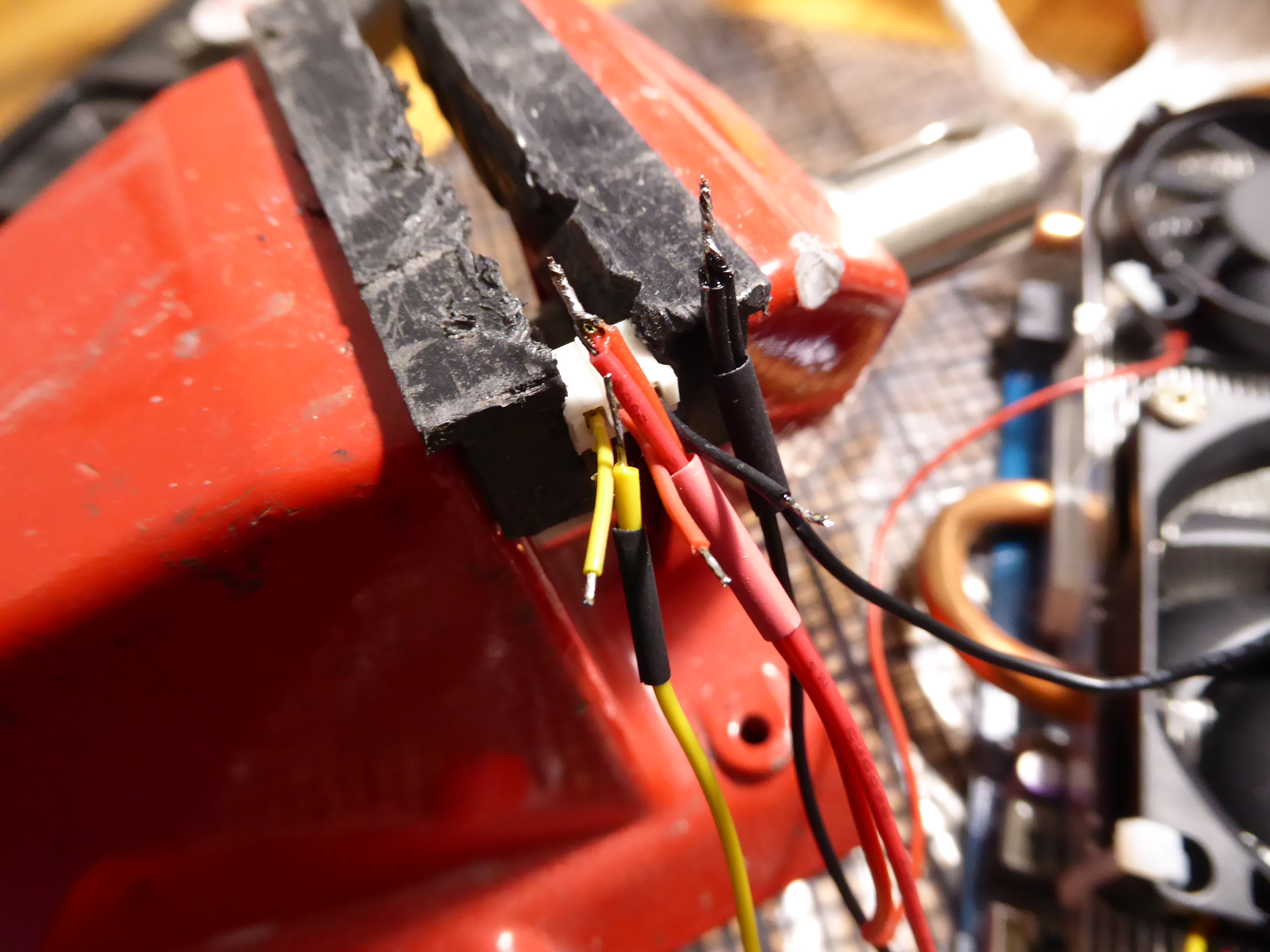
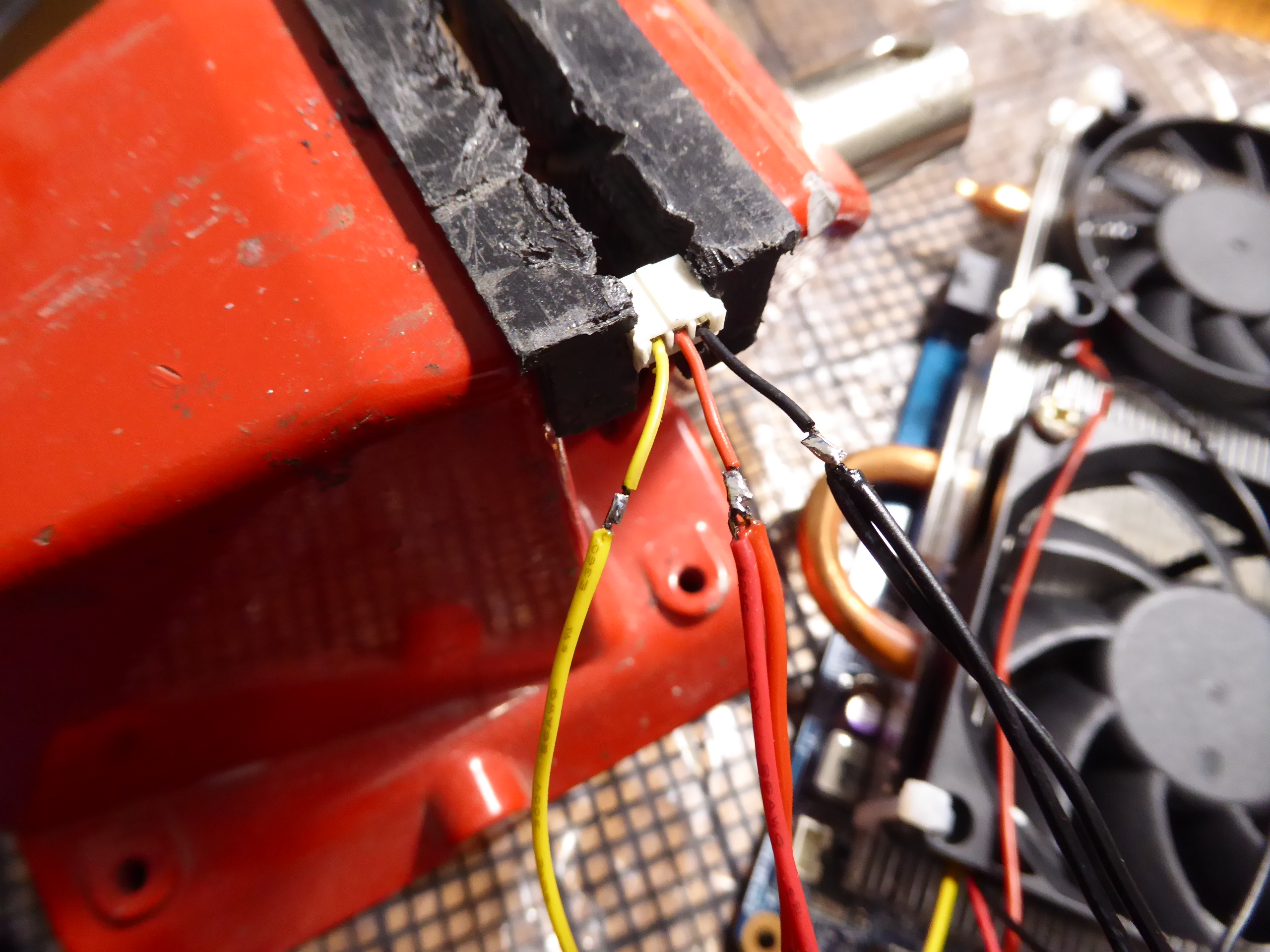
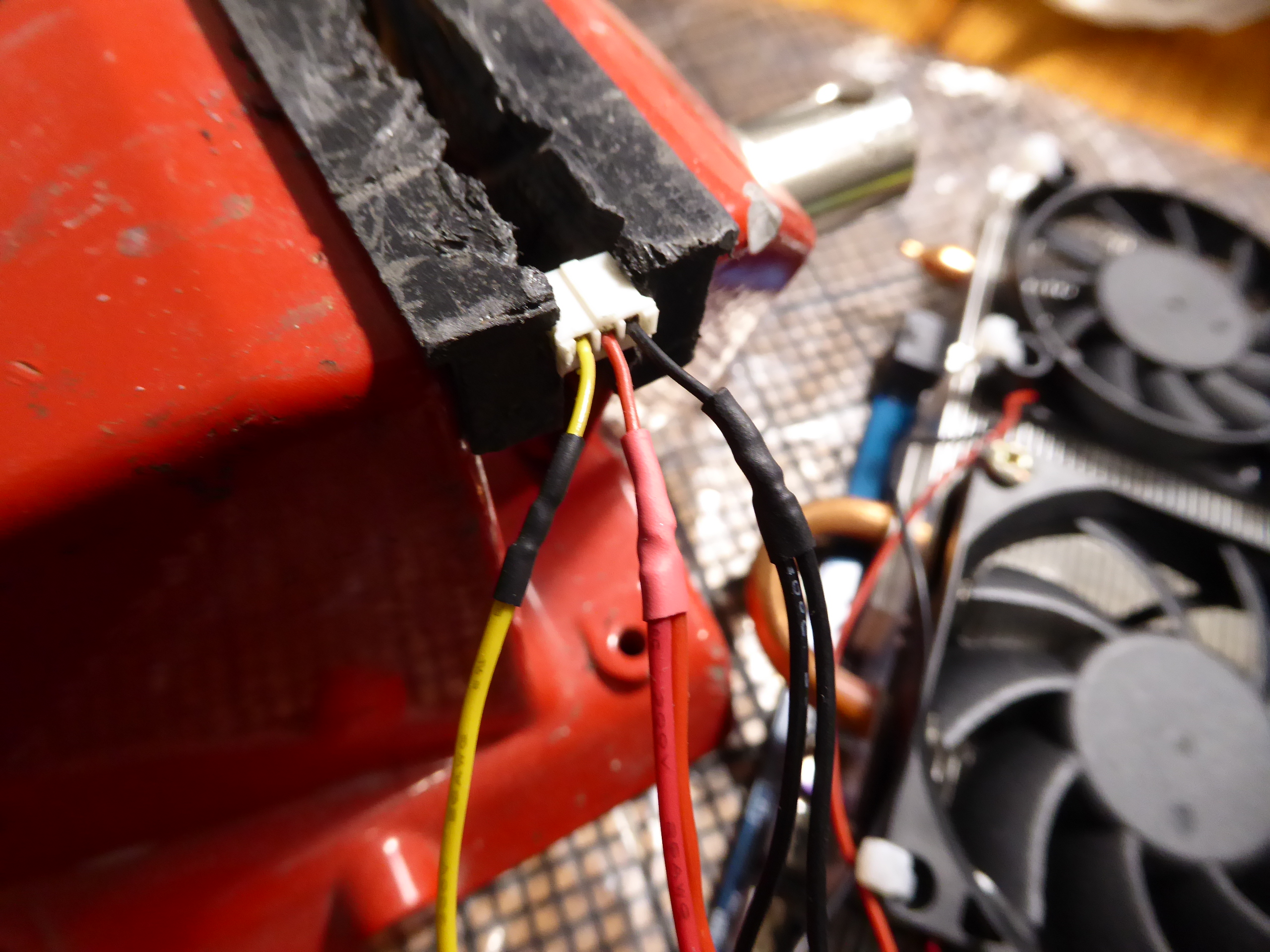
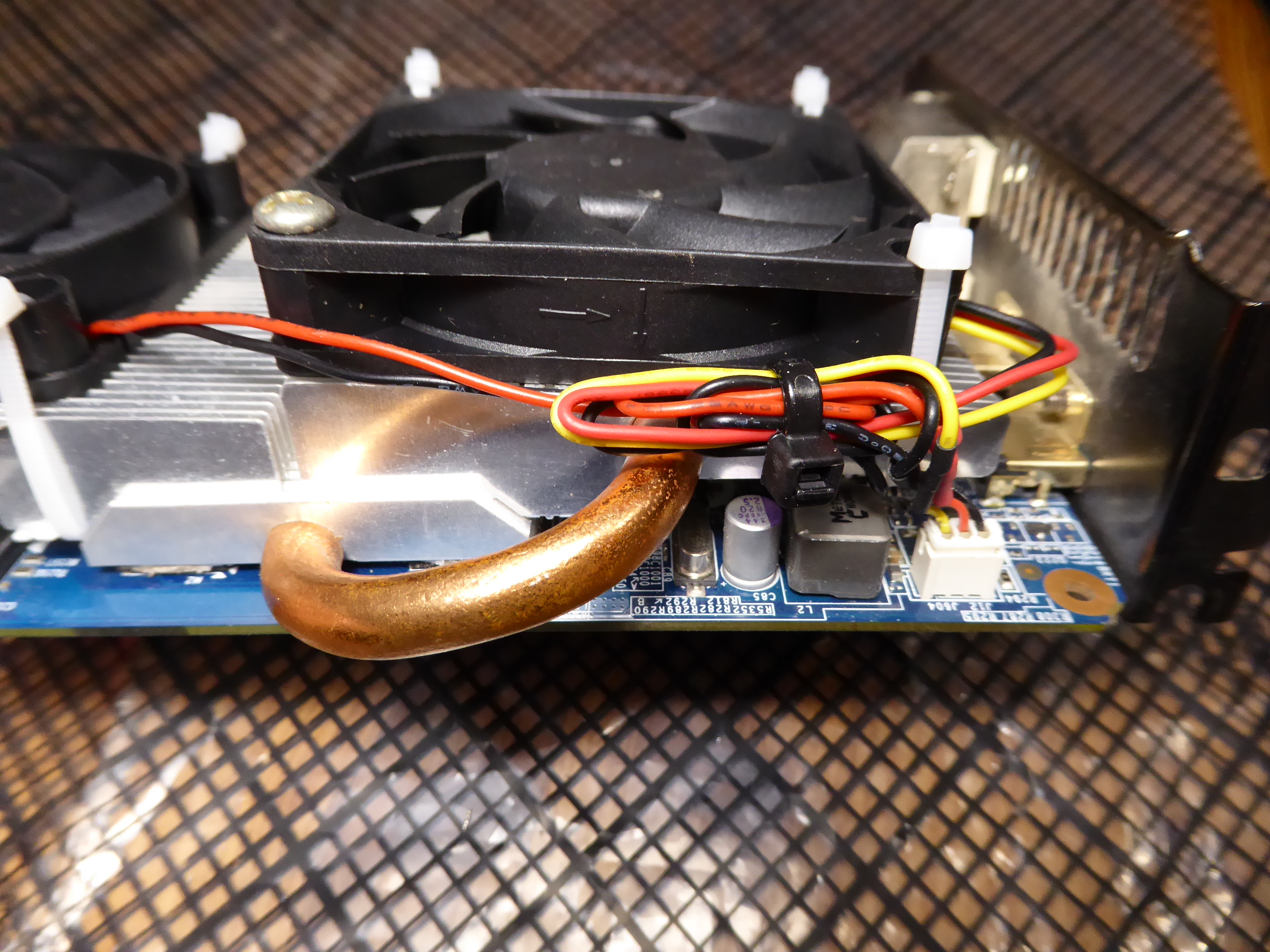
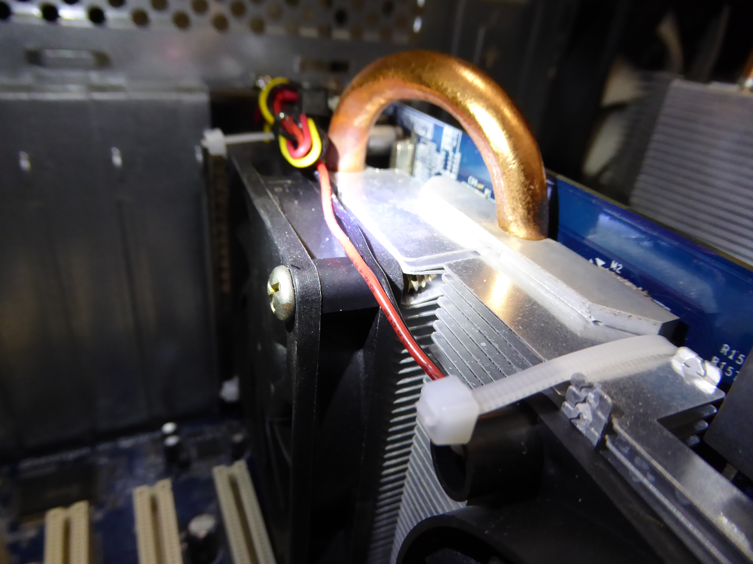
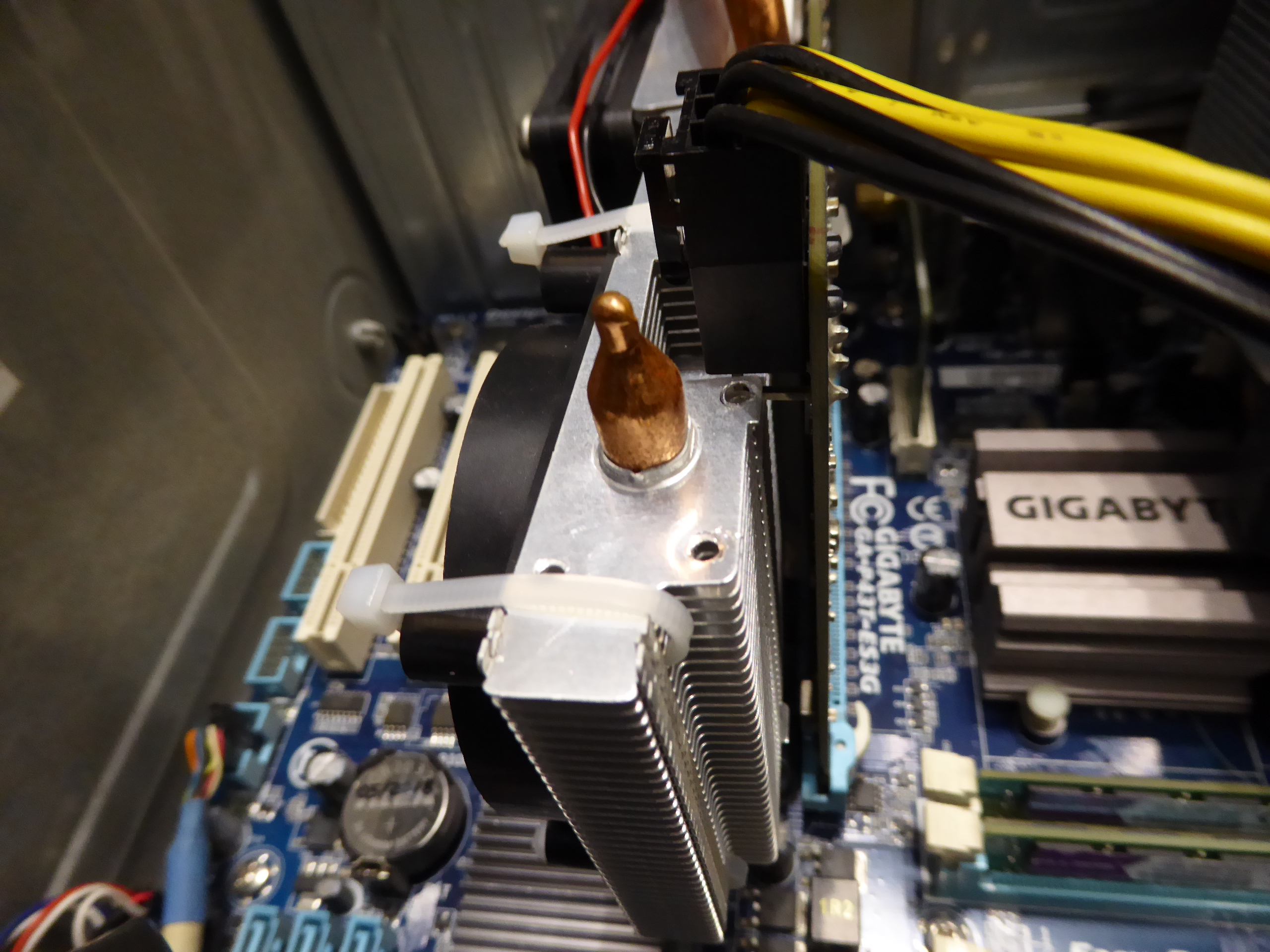
As of this kind rod4x4's suggestion: A Gigabyte graphics card based on a factory overclocked GTX 750 Ti GPU. After many years of intesive processing, both of its original fans became defective. Heading to retirement? No, if I can evite it... -1) Let's start by dismounting the fans frame. Now the heatsink is at sight. -2) By any chance, I had one 60x60x25 12 VDC fan, and another 70x70x25, this last with integral speed sensor. They seem to fit the heatsink very well. All mounting holes but one coinciding with pass-through fins. So let's arrange a cable tie for all of them (thank you, rod4x4), and a convenient screw for the exception. -3) Ok, now all fixings are in position. Time to electrical connections for both fans. -4) Starting by joining negative (black) and positive (red) terminals, and inserting heat-shrink sleeve to all cables. If both fans had speed sensor terminal (usually yellow), please, don't put them together. Use only one of them and isolate apart the other. And if different size fans, use the one of the biggest size (lower RPM) fan. Joining the speed sensor terminals from several fans, will interfere signals from each other. -5) Now we have soldered every terminals with the respective ones in card's fan connector. Previously, I've pulled backwards along the cables the heat-shrink sleeves. If not, they will shrink with heat coming from soldering. And if you forgot to insert previously the sleeves... now it is too late (you'll remember this when it happen:-) -6) This is the final look after shrinking the isolating sleeves with the heat of a gas burner. -7) And finally, we will arrange conveniently all cables and connect to fan's socket. Now we can compare this graphics card Before 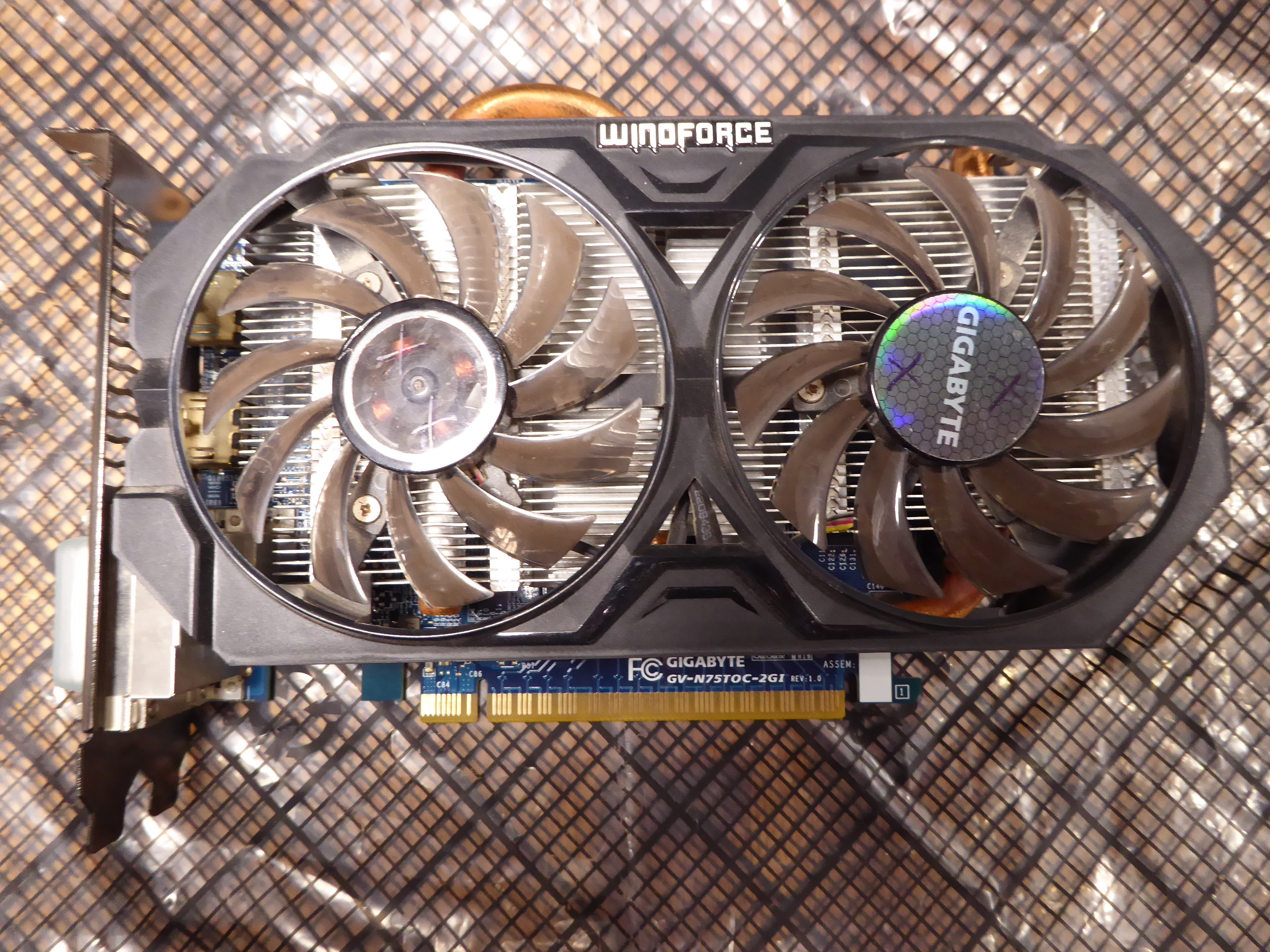 and After and After 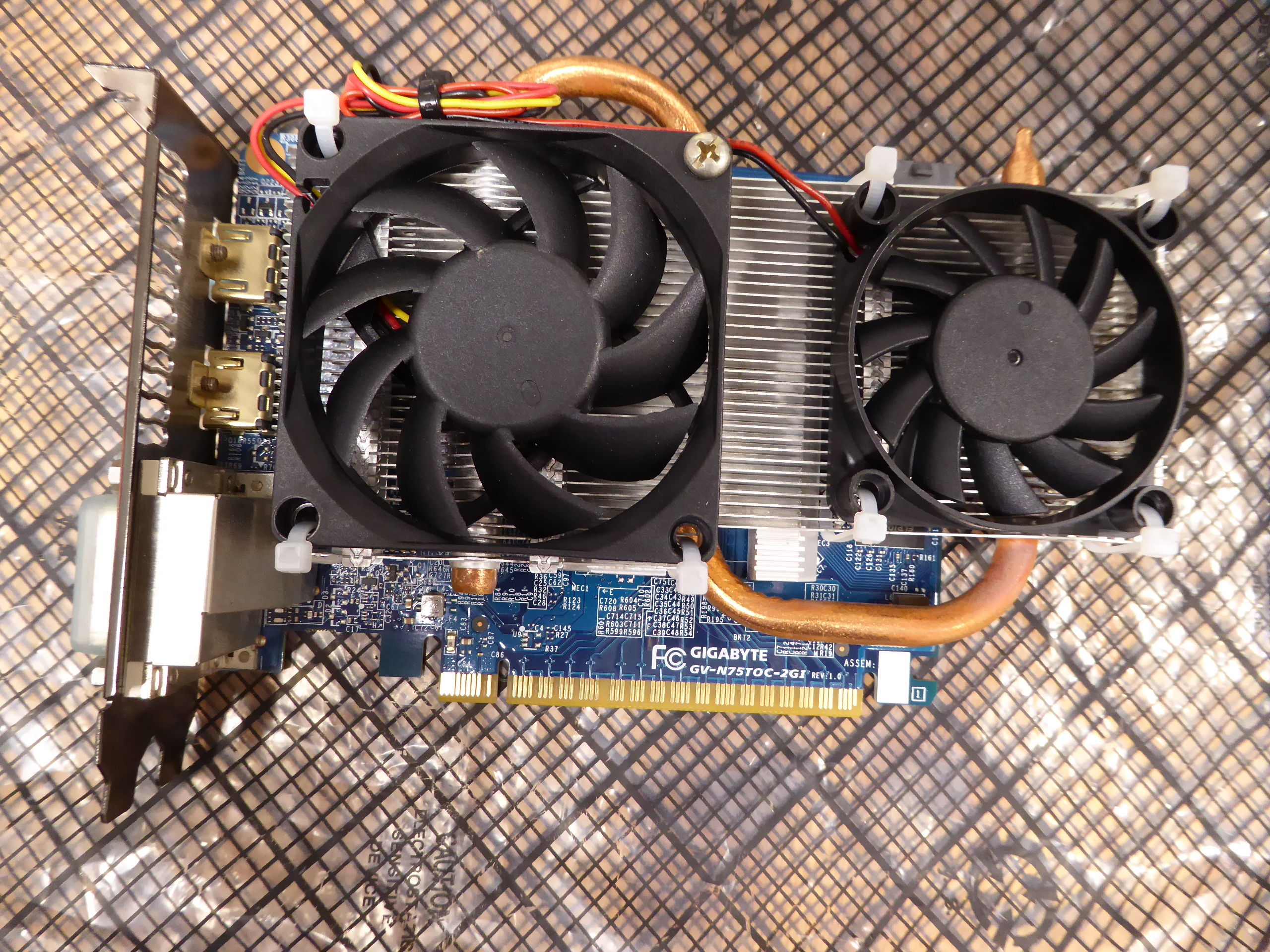 To test and take profit of this rescued card, I assembled this system. That's this: 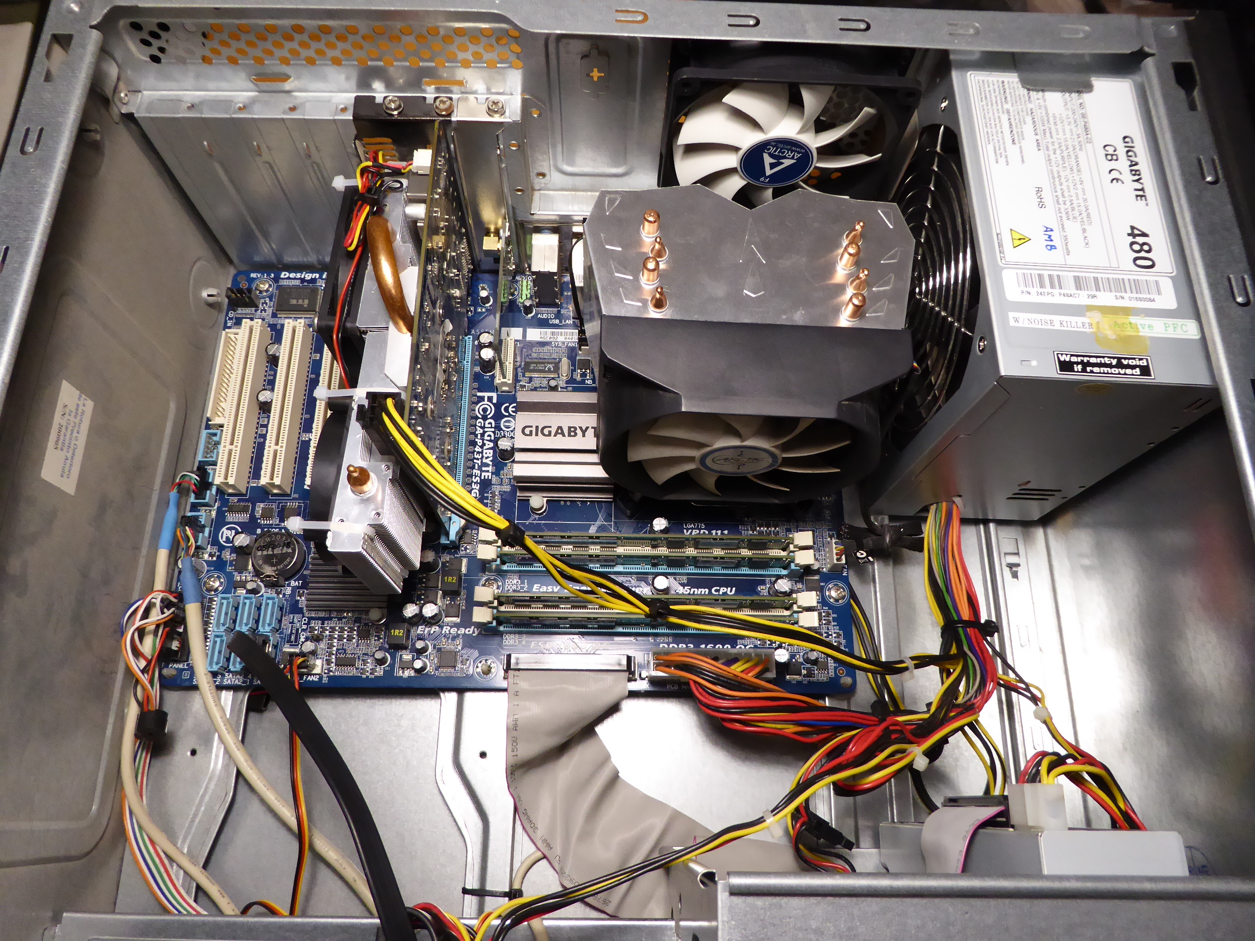 And it seems to be working fine, as can be seen at Psensor readings and finished tasks. 👍️ |
|
ServicEnginIC Send message Joined: 24 Sep 10 Posts: 595 Credit: 13,083,686,510 RAC: 745,928 Level Scientific publications |
Some corrections to my previous post: By any chance, I had one 60x60x25 12 VDC fan, and another 70x70x25, this last with integral speed sensor. For being more precise: The true dimentions for both fans were 60x60x12 mm and 70x70x15 mm. And I didn't have those fans "by any chance". I like to have assorted spare fans, because this component is a relatively frequent failing one... I'll also add a close detail for screw fixing and cable tie fixing. And two more curiosities: - I found the mentioned graphics card's invoice. I purchased it on 01/16/2015. Cost (taxes included): 159,00 € - After about one week of working in its "new life", this card has successfully processed 27 GPUGrid tasks, with no errors so far. |
|
Send message Joined: 4 Aug 14 Posts: 266 Credit: 2,219,935,054 RAC: 0 Level Scientific publications |
-1) Let's start by dismounting the fans frame. Now the heatsink is at sight. Great work and attention to detail. My Fans are cable tied very roughly, nowhere near as good as your setup. Another option for powering the fans and bypass the soldering stage (I am very lazy), is to use a free Chassis fan header on the Motherboard and set it to around 50% (depending on environment and fan size) or just use a molex adapter to fan 3 pin with a voltage reducing cable. Currently running GTX750 and GTX750ti with case fans. |
|
Retvari Zoltan Send message Joined: 20 Jan 09 Posts: 2380 Credit: 16,897,957,044 RAC: 0 Level Scientific publications |
TGC has solidified on another GPU (RTX 2080Ti this time) in one of my hosts. It was completely gone from the silicone itself, the markings of the chip left their mirrored print on the heatsink. I'm suspecting that I put too little amount of TGC on these GPUs, in fear of spilling it on the PCB around the GPU chip (full of SMD capacitors). It's much easier to put on the TGC for the second time, as it makes the solidified part liquid again, or at least the fresh TGC spreads on it very well without cleaning the surface. If the TGC reacts with the copper of the heatsink (as I suspect), leaving the "used" TGC on its surface may prevent further reaction between the two materials. I'll see, and report. |
|
ServicEnginIC Send message Joined: 24 Sep 10 Posts: 595 Credit: 13,083,686,510 RAC: 745,928 Level Scientific publications |
Thank you very much for your feedback |
|
Send message Joined: 29 Mar 20 Posts: 22 Credit: 968,641,468 RAC: 4,203 Level Scientific publications |
I read this thread and decided to shut down my computer and blow my heat sinks out with Office Depot Cleaning Duster. *COUGH COUGH COUGH* Large dust cloud!! I guess 2 years is a bit long to wait. |
|
ServicEnginIC Send message Joined: 24 Sep 10 Posts: 595 Credit: 13,083,686,510 RAC: 745,928 Level Scientific publications |
I read this thread and decided to shut down my computer and blow my heat sinks out... I applaud your decision. Computers are very avid dust-eating animals. And this can lead to indigestion if not treated on time... |
|
Send message Joined: 8 Aug 19 Posts: 252 Credit: 458,054,251 RAC: 0 Level Scientific publications |
Guys, I highly recommend Hydronaut by Thermal Grizzly. It beats both the Noctua and Arctic Silver thermal grease I was using by several degrees C. |
|
Send message Joined: 29 Mar 20 Posts: 22 Credit: 968,641,468 RAC: 4,203 Level Scientific publications |
It filled the room, lol. I had to leave for a few minutes. |
|
Send message Joined: 11 Jul 09 Posts: 1639 Credit: 10,159,968,649 RAC: 0 Level Scientific publications |
May I ask you hardware enthusiasts to double-check my thoughts on running BOINC on the new RTX 3070/3080/3090 range? I've been studying NVIDIA A100 Tensor Core GPU Architecture and NVIDIA Ampere GA102 GPU Architecture BOINC uses the number of CUDA cores per SM, and a flops multiplier, to estimate the GPU's peak speed. I'm getting that the GA102 (and above, but not the A100) benefit from both an increase from 64 to 128 cores per SM, and the ability to process two FP32 streams concurrently. So I think that the current v7.16.11 BOINC client will rate the new cards at one-quarter of the flops reported by other tools. Can anybody confirm that? If it's true, I'll code a patch for the next release of BOINC. |
|
Send message Joined: 13 Dec 17 Posts: 1424 Credit: 9,189,946,190 RAC: 2 Level Scientific publications |
May I ask you hardware enthusiasts to double-check my thoughts on running BOINC on the new RTX 3070/3080/3090 range? I think you are correct Richard. Basically you will have to duplicate your fix for the Pascal to Turing transition for CUDA cores per SM in reverse for the Ampere cards. 128 cores per SM for Ampere and the two concurrent FP32 pipelines. Would be best for someone with and actual card running and BOINC 7.6.11 running to report what BOINC shows for computed GFLOPS. |
|
Send message Joined: 11 Jul 09 Posts: 1639 Credit: 10,159,968,649 RAC: 0 Level Scientific publications |
Would be best for someone with and actual card running and BOINC 7.6.11 running to report what BOINC shows for computed GFLOPS. Absolutely - yes, please. Ray Hinchliffe has shown me a SIV report of 29,768 GFlops for an RTX 3080, and of 37,461 GFlops for an RTX 3090 - but those are still calculated values, albeit using a different method. He has a card on delivery, but my local supplier is still awaiting stock - and rationing orders to one per customer in the early days. |
|
Send message Joined: 13 Dec 17 Posts: 1424 Credit: 9,189,946,190 RAC: 2 Level Scientific publications |
I saw a note that EVGA is expecting "thousands" of 3080 chips into inventory in the future. I am still awaiting the hybrid version to appear on their website. No bites yet on the OCN forums about anyone running BOINC yet and reporting the calculated GFLOPS in the BOINC startup. |
|
ServicEnginIC Send message Joined: 24 Sep 10 Posts: 595 Credit: 13,083,686,510 RAC: 745,928 Level Scientific publications |
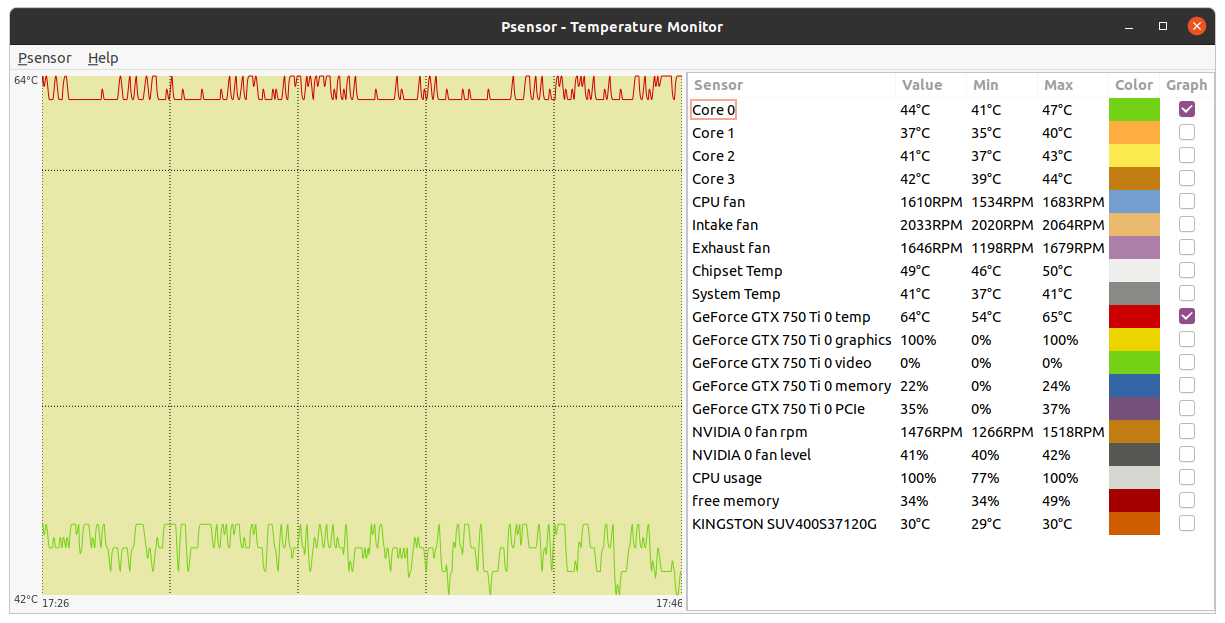
Let's begin this post with a thermal experiment: - We're going to start by setting into refrigerator two lemonade/beer jars filled 3/4 with tap water. - We wait for them to reach 5 ºC - Then we take one of the lemonade/beer jars, we put it into microwaves oven, and run it full power until water boils (100 ºC) - So far, everything is ok. (Now, for example, we can prepare an instant soup with that boiling water...) - WARNING! Please, DON'T follow subsequent steps in this experiment if you appreciate your lemonade/beer jar. - Now we take the second lemonade/beer jar from refrigerator, empty hot jar, and fill it with water from cold jar... May be nothig happens, but you have a high chance for the hot jar to crack! (Yes, I confess... I've cracked once a jar after prepairing an instant soup :-) The thermal trip from 5 ºC to 100 ºC is the same than from 100 ºC to 5 ºC... The difference is in the sudden of the thermal change in the second example. Now, the relationship of this experiment with high power electronics, as graphics cards GPU chips. Directly, I'm inserting an image with Psensor graphics. 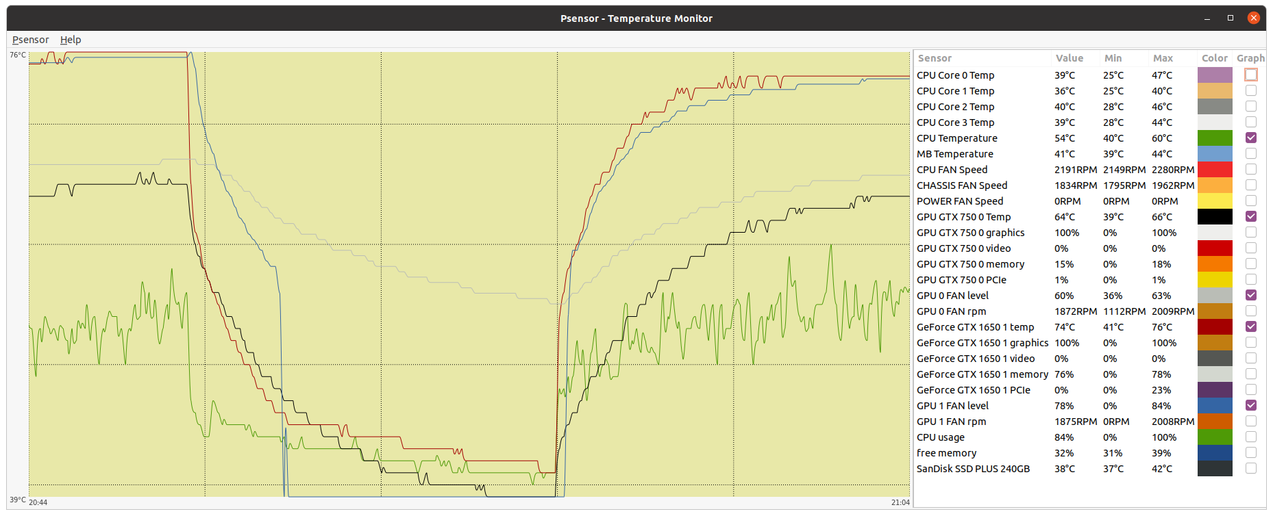 You can ctrl + click over it to have a full size image opened in a new browser tab. It is a true image taken from this double GPU system. I'm explaining this mess of curves and data: Graphic starts with about 4 minutes of system state while CPU and both GPUs running at 100% usage. It is followed by about 8 minutes with BOINC activity suspended, thus the whole system working at a residual low % usage. And finally, BOINC activity is restored, and system has passed from idle to 100 % usage again. Red and blue graph are associated respectively to GPU 0 Temperature and Fan level. While GPU 0 temperature is 76 ºC at full load, fan level is running 84%. When GPU 0 activity is suspended, GPU temperature starts decreasing (red curve), followed also by fan level (blue curve). This is factory configured this way, for achieving a more gradual GPU chip cooling figure (remember preceeding second jar example) On this particular GTX 1650 graphics card, when GPU chip temperature drops below 45 ºC, fans are completely stopped (0% level) for cooling to be even more gradual. Long time ago, I decided that playing with overclocking was a very mind-energy consuming activity. Currently I leave the job on manufacturer's hands, and I directly purchase factory overclocked graphics cards. And my particular self-acquired custom: I prefer leaving factory programmed fan curves untouched. So far, it is empirically confirmed by ten years of intense GPU processing without any of my squeezed GPUs becoming electrically broken. I still conserve operative my first crunching graphics card, based on a GTS 450 GPU, and my second one, based on a GTX 650 Ti Boost, both replaced by newer models. As always, experiences from other users are welcome. For example, I have no personal background with water cooling. Theoretically, it should be the best way for eviting thermal stress affairs, right? |
|
Send message Joined: 13 Dec 17 Posts: 1424 Credit: 9,189,946,190 RAC: 2 Level Scientific publications |
My cards are all still alive and working after ten years or more. Going all the way back to a GTX460. Cards never had much thermal stresses in their lifetime. Cards got installed and then immediately run 24/7 at 100% fan speed until they were replaced with the next generation. Then pulled and put on the shelf. I also always ran a very mild core overclock of 0-40Mhz depending on the card and thermal environment. I also always ran a significant memory overclock of 400-2000Mhz to compensate for the Nvidia compute penalty on consumer cards depending on the card generation. |

©2026 Universitat Pompeu Fabra